
Product Short Description
Product Overview
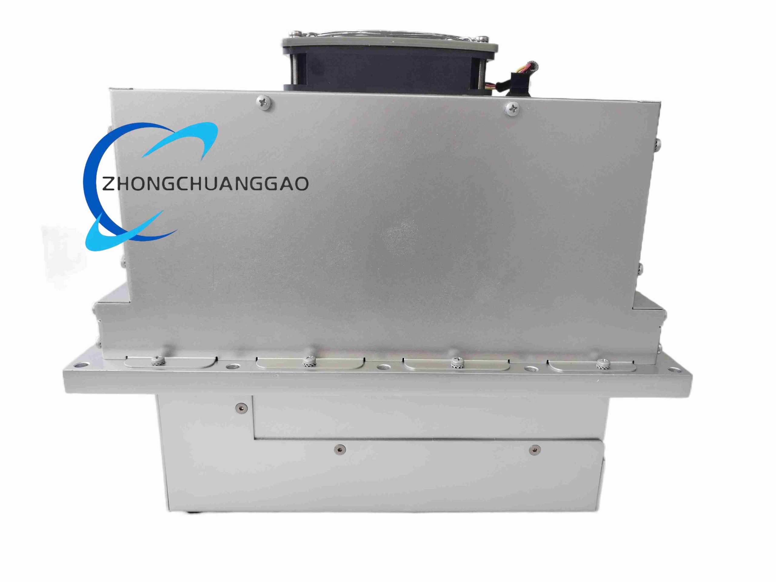
This high-power air-cooled servo inverter is purpose-built by LTi Drives for horizontal axis wind turbine pitch control systems. It delivers precise high-torque speed and position closed-loop control for permanent magnet pitch servo motors, regulating wind turbine blade pitch angles to optimize power generation efficiency and implement emergency feathering protection during overspeed, grid loss or extreme wind conditions.
Description
Core Technical Specifications
- Rated Input Power: Three-phase 400VAC industrial mains input, 50/60Hz
- Continuous Output Current Rating: 54A three-phase AC output, matched to multi-kilowatt pitch servo motors
- Control Algorithm: Field-oriented vector control (FOC), 32-bit floating-point high-speed position loop processor
- Position Control Accuracy: ±0.01° pitch angle positioning repeatability, 16-bit encoder resolution support
- Built-in Safety Functions: STO (Safe Torque Off) safety circuit, overspeed protection, overvoltage DC bus clamping, thermal motor protection
- Communication Interfaces: CANopen pitch control bus, RS485 serial diagnostic port, incremental encoder feedback interface
- Cooling System: Forced air convection cooling with built-in high-temperature resistant axial fan and large aluminum fin heat sink
- Operating Ambient Temperature: -20°C ~ +50°C wind turbine nacelle cabinet environment
- Storage Temperature Range: -40°C ~ +85°C
- Environmental Protection Rating: IP20 for control cabinet internal installation
- Shock & Vibration Standard: Compliant with IEC 61400-1 wind turbine mechanical vibration test standards
- Physical Structure: Vertical panel mounting unit with integrated bottom heat sink, integrated terminal block wiring compartment
- Compliance Certifications: CE Low Voltage Directive, EMC Directive, Machinery Directive 2006/42/EC, wind turbine GL certification
Function & Performance Features
- High dynamic torque response: Full rated torque output at zero motor speed for fast blade feathering emergency action
- Dual closed-loop control architecture: Outer position loop for target pitch angle tracking, inner current/torque loop for smooth motor operation
- Active DC bus overvoltage suppression circuit to absorb regenerative energy generated during blade deceleration
- Redundant safety STO circuit compliant with PLd SIL2 functional safety standard for wind turbine pitch safety protection
- Multiple fault diagnosis logic: Motor winding over-temperature, encoder signal loss, mains phase loss, IGBT over-temperature, short-circuit output protection
- Programmable pitch motion profile: Acceleration, deceleration, jog speed, emergency feather speed fully configurable via LTi PC configuration software
- CANopen bus real-time data exchange with wind turbine main controller; transmits pitch angle, motor temperature, drive fault status and torque feedback
- Built-in fault event storage records 100+ historical fault codes with timestamp for post-failure nacelle maintenance analysis
Working Principle
Three-phase 400VAC mains input is rectified to high-voltage DC bus inside the drive unit. The internal IGBT power inverter module converts DC bus voltage to variable frequency variable amplitude three-phase AC power to drive the permanent magnet pitch servo motor. High-resolution encoder feedback signals return motor actual position and speed to the drive’s 32-bit control processor, which continuously adjusts output voltage frequency to minimize deviation between measured pitch angle and target angle set by the wind turbine main controller. When grid failure or turbine overspeed fault signal is received, the STO safety circuit cuts motor torque output instantly while executing pre-programmed emergency feather motion curve to rotate blades to safety stop position. Regenerative energy from decelerating blades is absorbed by built-in braking resistors to stabilize DC bus voltage.
Material & Structural Composition
- Main housing: Thick galvanized steel sheet with corrosion-resistant paint coating for nacelle high-humidity environment
- Heat dissipation assembly: Extruded aluminum alloy fin heat sink, high-temperature bearing cooling axial fan with dust filter mesh
- Power stage components: High-current IGBT power modules, low-inductance DC bus film capacitors, wire-wound braking resistors
- Control circuit PCB: Multi-layer FR4 industrial circuit board with conformal coating to resist condensation and salt mist corrosion
- Wiring terminals: High-current copper alloy screw terminal blocks with plastic insulating protective cover for power and signal wiring separation
Installation Requirements
- Must be vertically mounted inside wind turbine nacelle control cabinet; horizontal or inverted mounting strictly forbidden to avoid heat sink airflow obstruction
- Maintain minimum 150mm vertical clearance above and below the drive unit for cooling fan airflow circulation
- Three-phase motor power cables must use shielded symmetrical servo motor cables with 360° metal shield termination at drive terminal side
- Separate high-current power wiring and low-level encoder signal wiring into isolated cable ducts with minimum 50mm separation distance
- Connect dedicated heavy copper protective earth wire (≥6mm² cross-section) from drive chassis to nacelle cabinet grounding bar
- Install nacelle cabinet heating and dehumidification equipment to prevent internal condensation in cold coastal wind farm environments
- Perform 2-hour full-load dynamic pitch cycle test after installation to verify thermal stability of heat sink and fan assembly
Typical Application Scenarios
- Onshore horizontal axis megawatt-class wind turbine pitch control nacelle systems
- Offshore coastal wind farm turbine blade angle regulation drive units
- Hybrid wind-solar energy storage turbine pitch safety control equipment
Mandatory Operation & Maintenance Precautions
- Wait minimum 30 minutes after drive power shutdown before opening cabinet covers to allow DC bus capacitors full discharge to safe voltage (<50VDC)
- Only certified wind turbine electrical maintenance personnel are permitted to perform disassembly, wiring or parameter modification work
- Conduct quarterly inspection of cooling fan filter mesh to remove accumulated dust and insect debris that blocks airflow
- Semi-annually check power terminal block screw torque to prevent thermal loosening under nacelle vibration conditions
- Replace cooling fan bearing assembly every 3 years to avoid fan stall overheating drive power modules
- Do not bypass STO safety circuit interlock wiring during temporary maintenance testing
- Store spare drive units in temperature-controlled dry warehouse with anti-condensation packaging for offshore wind farm stock
Reviews
There are no reviews yet.