
Product Short Description
Product Introduction
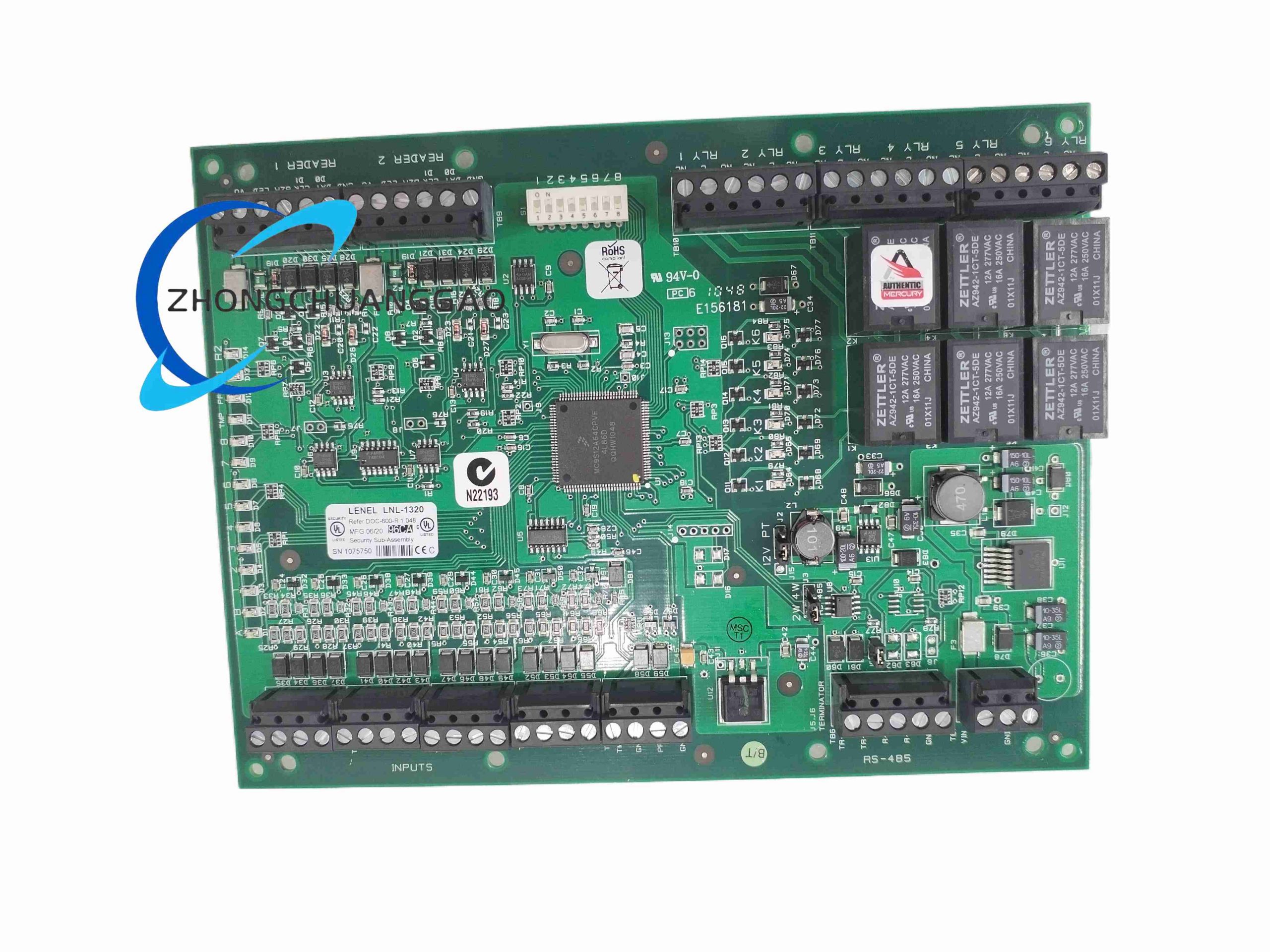
The LNL-1320 is an intelligent field hardware module belonging to the Lenel OnGuard access control platform. It serves as the interface between access control readers, door locking hardware and the access control network controller. The module supports one card reader, collects credential verification data, monitors door contact status, controls electric lock output and manages request-to-exit devices.
Description
Technical & Performance Specifications
- Communication Parameters
- Host Communication: RS-485 bus (Lenel proprietary bus protocol)
- Maximum bus cable length: 1200 meters
- Reader Interface: Supports Wiegand 26/34/40 bit protocol readers
- I/O Channel Definition
- 1 × Wiegand reader input port
- 1 × supervised door contact input (monitors door open/closed status)
- 1 × supervised request-to-exit (RTE) input
- 1 × relay output for electric lock control
- Auxiliary supervised input for alarm devices
- Electrical Ratings
- Operating Power: 12 VDC nominal input
- Module power consumption: <150 mA standby
- Lock Relay Contact Rating: 2 A @ 30 VDC resistive load
- Input circuit support end-of-line resistor supervision for tamper detection
- Physical & Environmental Specifications
- Mounting: 35 mm DIN rail or inside security door control cabinet
- Protection Class: IP30 indoor cabinet installation only
- Operating Temperature: 0°C ~ +50°C
- Storage Temperature: -20°C ~ +70°C
- Humidity: 0–90% non-condensing
- Status Indication
- Multi-color LED indicators for bus communication, reader activity, relay activation and fault status
Function Features
- Compatible with all standard Wiegand format proximity card readers, biometric readers and barcode credential readers
- Fully supervised input circuits utilizing end-of-line resistors; detects wire short-circuit, open-circuit and line tampering events
- Relay output controls magnetic locks, electric strike locks and motorized door locks
- Real-time capture of all access events, door forced open alarms, door held open alarms and RTE exit events
- Stores temporary event buffer locally when communication to main controller is interrupted; uploads cached data after communication recovery
- Supports configurable door time delay, anti-passback linkage and access schedule rules synchronized from OnGuard server
- Tamper monitoring capability for enclosure intrusion
- Plug-and-play integration with Lenel OnGuard access control management software platform
- Multiple LNL series modules can share a single RS-485 bus to reduce wiring workload
Working Principle
When a user presents an access credential to the connected Wiegand reader, the reader transmits card ID data to the LNL-1320 module. The module forwards credential information via RS-485 bus to the upper-level network controller. The controller compares credential data against access permission databases on the OnGuard server. If access is authorized, the module activates the lock relay to unlock the door for the configured duration. Door contact sensor continuously feeds door status signals back to the module. If a door remains open beyond the allowed time or is forced open without valid credential, the module triggers alarm messages and sends event records to the security management host. All input circuits continuously monitor line resistance to identify cable tampering attempts.
Material & Structural Composition
- Housing: Flame-retardant black ABS plastic enclosure
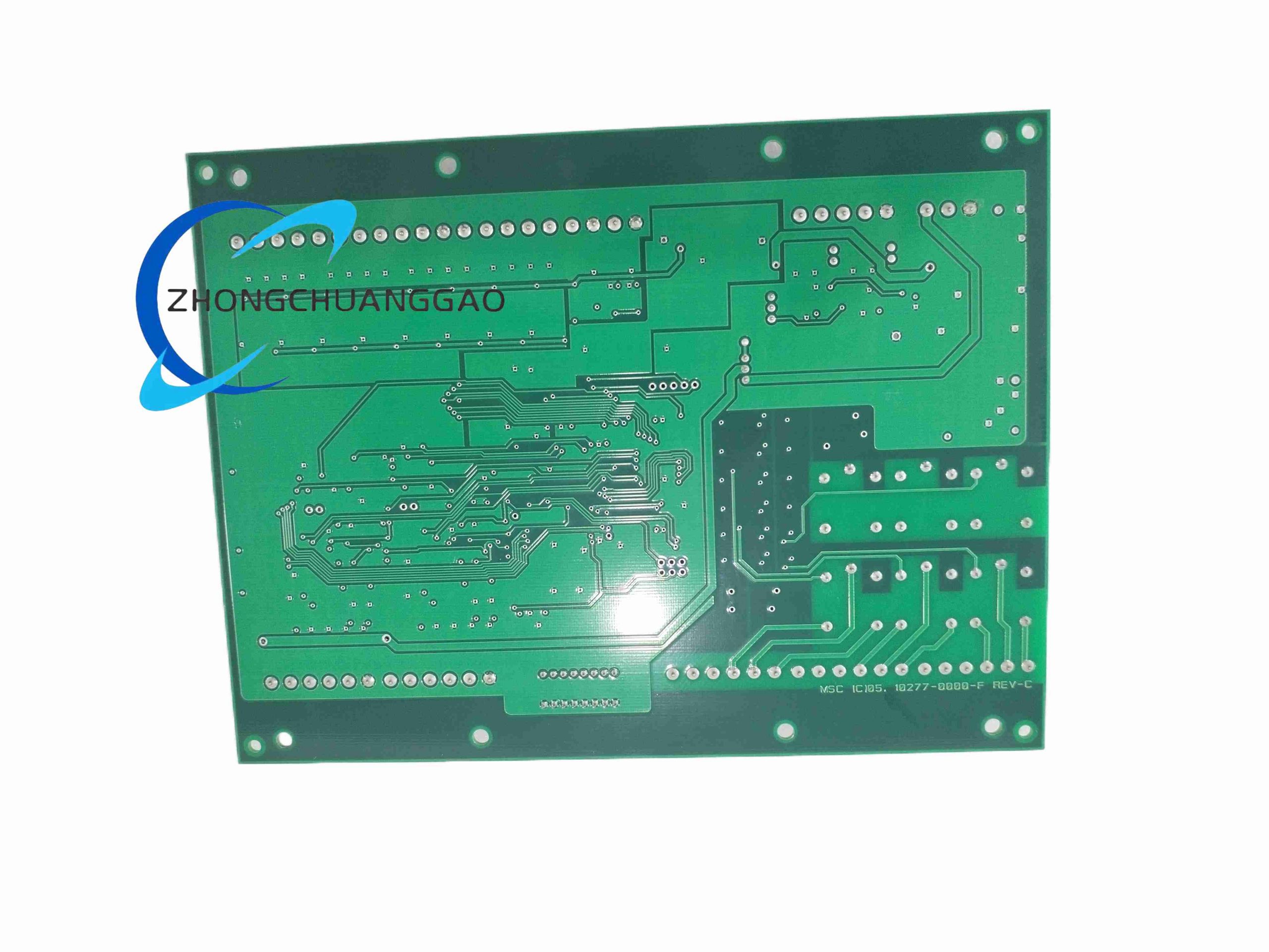
- Main Circuit Board: Double-sided FR4 PCB with silkscreen terminal marking
- Communication Chipset: Industrial RS-485 transceiver with ESD and surge protection
- Switching Component: Electromagnetic signal relay for lock drive output
- Terminal Blocks: Screw-type nickel-plated copper terminals with PA66 flame retardant insulation
- Mounting Hardware: Integrated DIN rail slide-on clip
- Protection Devices: TVS diodes and current-limiting resistors for surge protection on signal lines
Installation Requirements
- Install inside locked metal door control cabinet to prevent physical tampering
- All supervised input wiring must install specified end-of-line resistors at the far end of sensor cables
- Separate low-voltage signal wiring (reader, sensor cables) from high-current lock power wiring
- RS-485 communication cable must use twisted shielded cable; terminate bus ends with matching resistance resistors
- Provide stable regulated 12 VDC power supply; avoid shared power circuits with large inductive loads
- Maximum distance between module and Wiegand reader limited to 150 meters
- Cabinet PE ground connection required to reduce static and surge interference
Application Scenarios
- Office building single-door networked access control management
- Data center server room secure door access monitoring
- Hospital restricted area staff credential access control
- University campus laboratory and research facility access management
- Manufacturing factory administrative zone access security
- Retail headquarters and financial institution back-office door control
Usage Precautions
- Do not connect inductive loads directly to relay terminals without flyback suppression diodes
- Regularly inspect terminal screw tightness to avoid poor contact caused by temperature cycling
- When multiple modules share one RS-485 bus, strictly follow bus topology; avoid star wiring layout
- Shield grounding of communication cable should be implemented at control cabinet side only
- Prevent moisture ingress inside enclosure; condensation will cause input circuit misoperation
- Cut off power before modifying wiring configuration
- Conduct full function test of door contact, RTE and lock relay after installation or rewiring
Reviews
There are no reviews yet.