
Product Short Description
Product Name
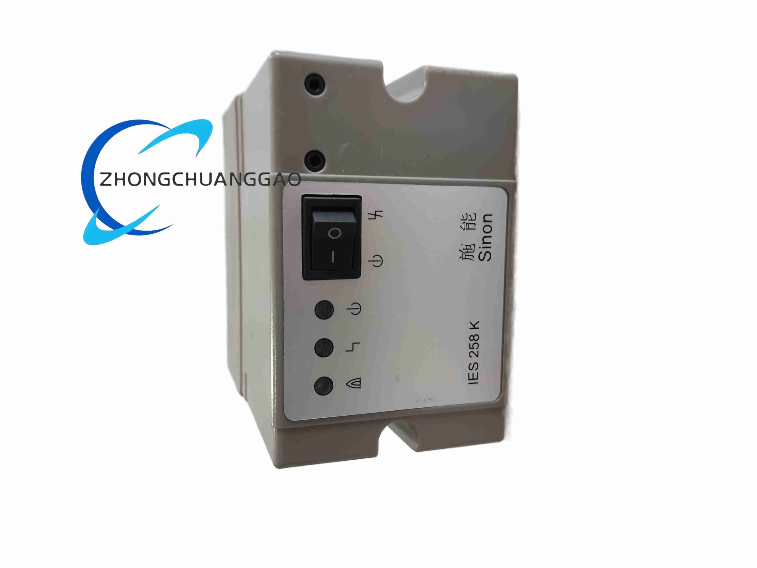
KROM Schroder IES258K automatic burner control unit with ignition and flame monitoring for gas burners.
Product Introduction
IES258K controls direct ignition and flame supervision for gas burners with or without forced combustion air. It supports ionization flame detection or ultraviolet flame detection and can use one electrode for both ignition and ionization monitoring. The controller is intended for systems where purge is omitted or performed by another control system.
Description
Technical Specifications
Supply voltage: two hundred twenty VAC, plus or minus ten percent, fifty Hz.
Power consumption: nineteen VA.
Maximum direct ignition burner power: three hundred fifty kW.
Flame detection current setting: adjustable from two to twenty microamperes for ionization mode.
High-voltage ignition cable length: less than one meter preferred.
Ionization sensor cable length: up to seventy-five meters.
Ultraviolet sensor cable length: up to one hundred meters.
Outputs: solenoid and ignition transformer outputs, maximum two amperes per output, total maximum two point five amperes.
Status contacts: normal-run contact and fault contact, maximum two amperes, maximum two hundred fifty-three VAC depending on contact rating.
Fuse: three point one five amperes slow-blow type according to IEC 127-2/5.
Enclosure protection: IP40.
Ambient temperature: minus twenty to plus sixty degrees Celsius, no condensation.
Service life: more than one million operations; single-electrode configuration exceeds two hundred seventy thousand operations according to product data.
Mounting: thirty-five millimeter DIN rail with approximately one hundred thirteen millimeter rail length, or screw mounting with hole spacing approximately seventy millimeters.
Body dimensions: approximately one hundred thirteen millimeters wide, seventy-five millimeters high, one hundred twenty millimeters deep.
Functional Features
Single-stage burner control with one gas valve output.
Ionization or ultraviolet flame proving.
Single-electrode ignition and flame signal return where ionization is used.
Flame loss lockout with alarm indication and manual reset after fault clearance.
Separate normal operation and fault relay contacts.
Adjustable ionization threshold for different flame electrode and burner conditions.
Application Scenarios
Forced-air gas burners up to three hundred fifty kW direct ignition rating.
Atmospheric gas burners in ovens, dryers, and thermal process equipment.
Systems where external controller performs purge and IES258K performs ignition and monitoring.
Continuous or modulating burners when used with external temperature or air/fuel ratio control.
Single-valve industrial heating zones requiring proven flame safety lockout.
Performance Parameters
Ionization detection responds to flame rectification current within the two to twenty microampere adjustment range.
Ultraviolet detection operates with KROM Schroder UV detector within the stated cable distance.
Ignition transformer output energizes the spark electrode through the controller output stage.
Lockout occurs when flame signal is absent after ignition time or when established flame is lost.
Contact outputs report burner-on and fault states to PLC, annunciator, or safety circuit.
Materials And Construction
Molded industrial enclosure with IP40 rating.
Screw or spring terminal block according to supplied variant.
Internal ignition transformer driver, flame-signal amplifier, relay outputs, and fuse holder.
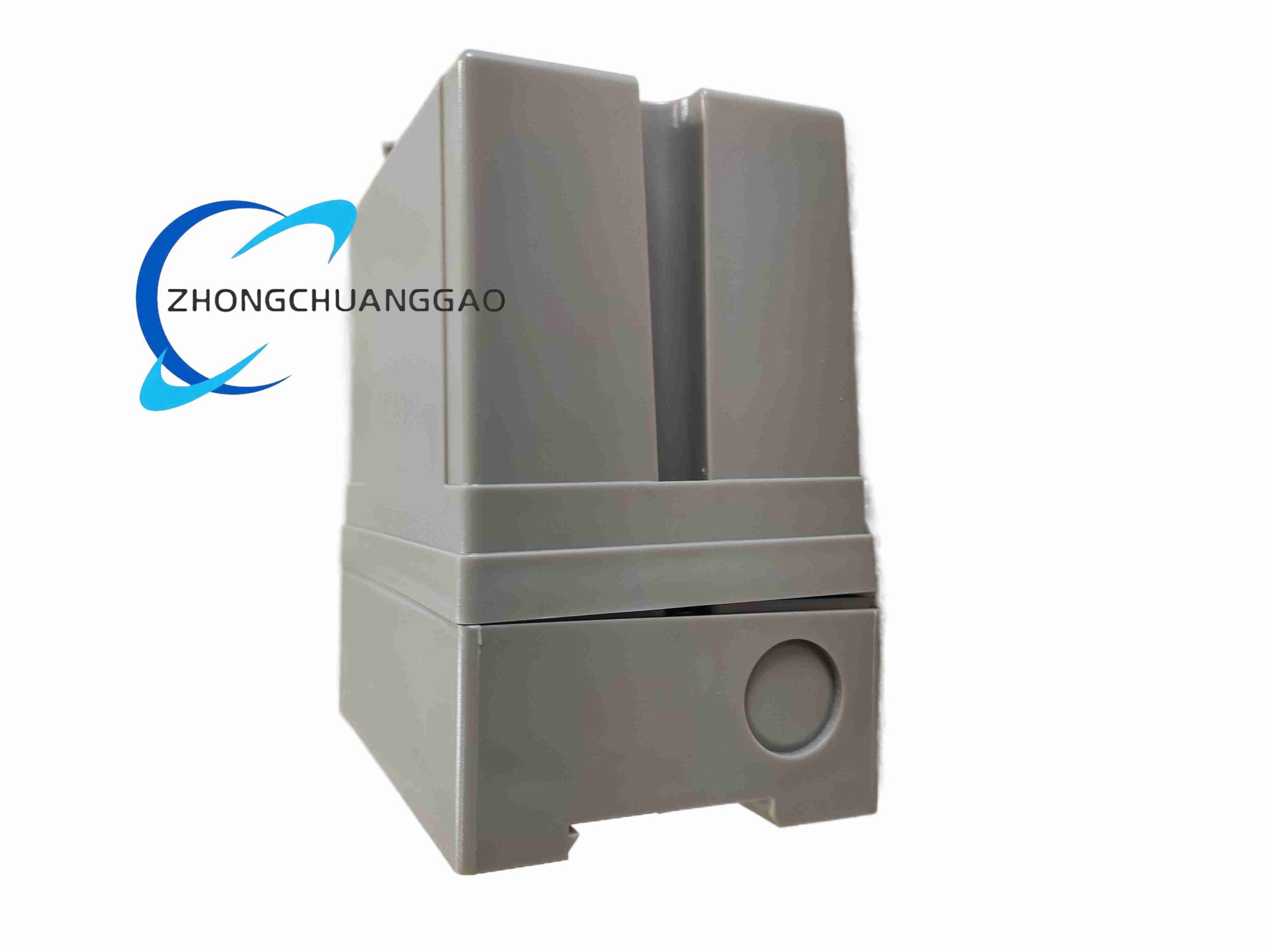
DIN-rail clip and panel-mounting holes integrated in the housing.
Working Principle
The controller applies AC supply to the ignition transformer and gas valve output in the programmed ignition sequence. During ionization monitoring, the flame acts as a rectifier between the electrode and burner body; the controller measures DC rectified current and compares it with the set threshold. During ultraviolet monitoring, the UV detector converts flame radiation into electrical pulses and the controller evaluates flame presence. If no valid flame signal is detected or flame is lost, the controller de-energizes the valve, activates the fault contact, and remains locked until manual reset.
Installation Requirements
Mount on 35 mm DIN rail or screw-fix to panel with the stated hole spacing.
Connect L and N supply terminals with correct polarity; do not reverse live and neutral.
Keep high-voltage ignition cable shorter than one meter and away from low-voltage sensor wiring.
Use separate conduit or cable path for ionization lead when cable length exceeds five meters.
Ground terminal seven when using single-electrode ionization; do not ground terminal seven when using UV detector.
Usage Precautions
Verify burner direct-ignition power does not exceed three hundred fifty kW for this controller class.
Do not replace the slow-blow fuse with a fast-acting or higher-rating fuse.
Confirm ionization versus UV configuration before first start; mixing electrode grounding rules causes detection failure.
Reset only after the alarm condition is cleared and burner safety check is complete.
Prevent condensation, dust buildup on terminals, and unauthorized modification of flame threshold settings.
Reviews
There are no reviews yet.