
Product Short Description
Product Overview
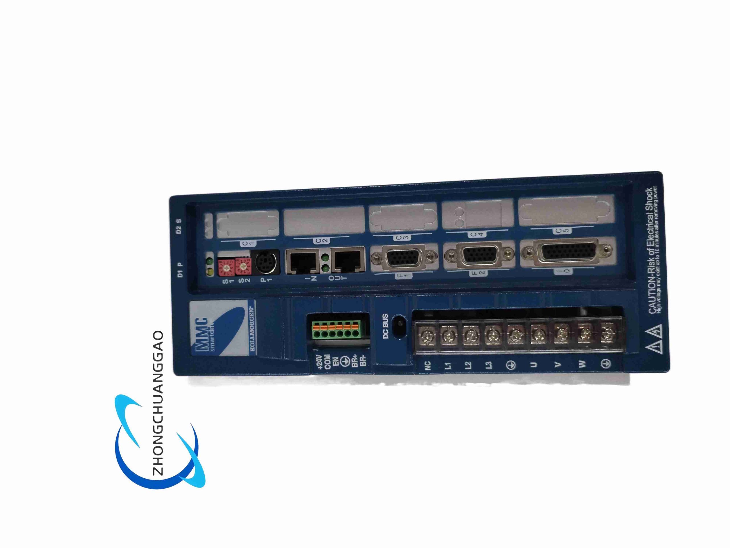
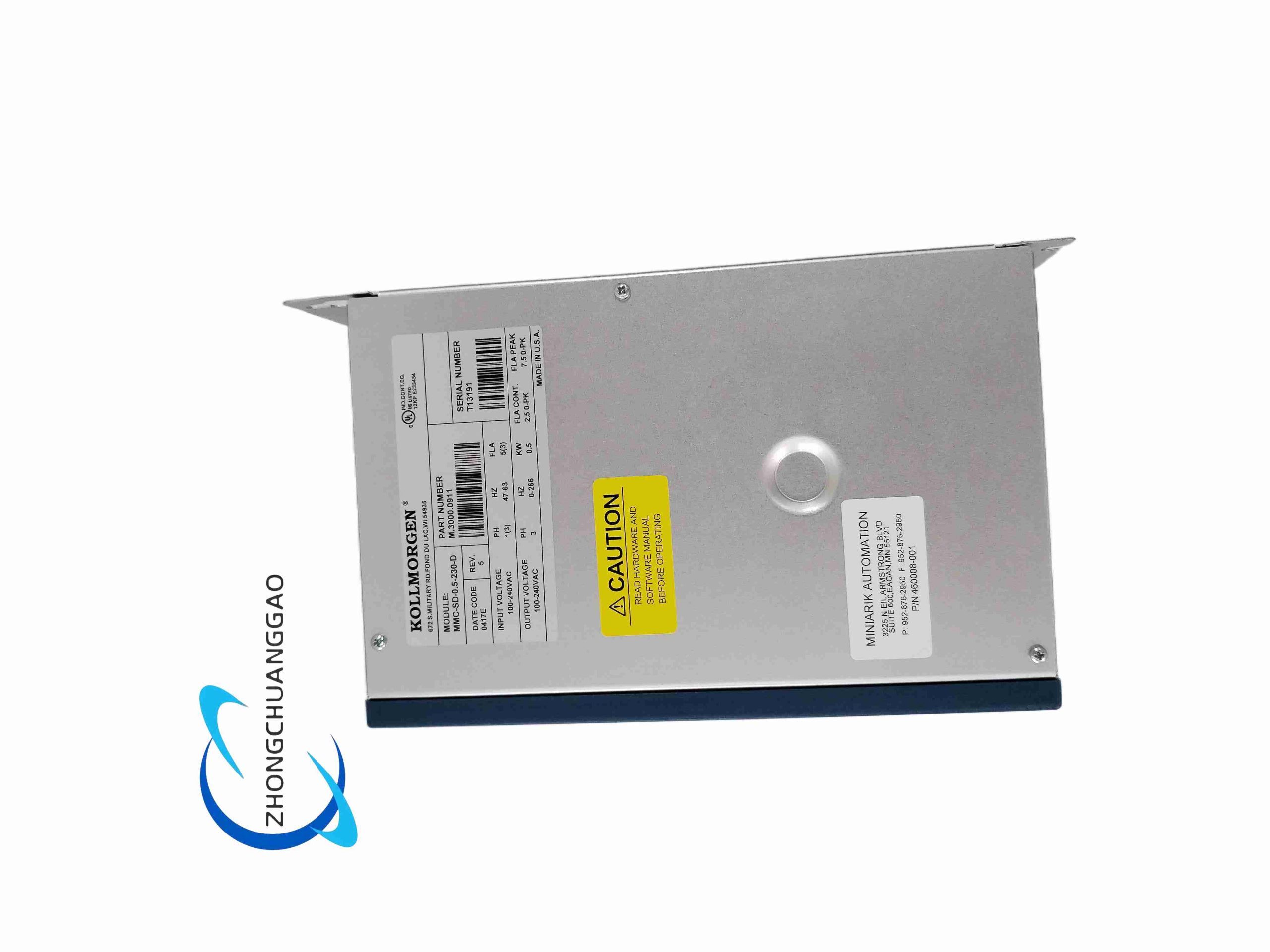
MMC-SD series is compact high-efficiency digital servo drive platform for low-power precision servo applications. Model breakdown: 0.5 = 0.5 kW rated output power, 230 = 115/230 VAC single/three-phase input voltage class, D = Digital high-speed motion bus interface variant (Digital Link bus for Kollmorgen MMC motion controller connection). It integrates rectifier, IGBT power inverter, position loop processor and multi-channel I/O into single compact unit, supporting full closed-loop torque/velocity/position control for small frame AKM series permanent magnet servo motors.
Description
Core Technical & Performance Parameters
- Rated output power: 0.5 kW; Continuous RMS output current: 2.5 A
- Peak RMS output current: 7.5 A (300% overload capacity for 5 seconds maximum)
- Main power input: Single or three-phase 115–230 VAC, 50/60 Hz
- Separate logic control power: 24 VDC ±10 V, 0.4 A independent supply
- PWM switching frequency: 16 kHz low-noise high-frequency modulation
- Feedback support: Incremental TTL encoder, resolver analog feedback
- Communication interface: MMC Digital Link dedicated motion bus, RS232 configuration port
- Built-in digital I/O: 8 programmable 24 VDC inputs, 4 high-speed digital outputs
- Analog interfaces: ±10 V velocity/torque command input, 0–10 V analog monitor output
- Protection class: IP20 (cabinet internal installation only)
- Operating temperature: 0°C ~ +55°C; Derate power output 10% above 45°C ambient
- Physical dimension: 45 mm width × 130 mm height × 110 mm depth, DIN rail mountable
- Weight: 0.82 kg; Maximum cable wire gauge for power terminals: 1.5 mm²
Function Features
- 16 kHz high-frequency PWM output minimizes motor audible noise and winding heating, improves low-speed smooth running performance below 10 rpm.
- 300% instantaneous peak overload torque enables fast acceleration for small precision automation axes without oversizing drive hardware.
- Dual independent power supplies (main AC power + 24 VDC logic power) maintain control circuit operation during momentary mains voltage drop, retaining fault state recording.
- Multi-mode control switching: Torque mode, velocity mode, position mode, master-slave electronic gearing mode configurable via software parameters.
- Comprehensive multi-layer protection: Overcurrent, overvoltage, undervoltage, overheat, encoder loss, motor phase loss, IGBT short-circuit hardware lockout protection.
- Automatic motor parameter identification function; one-click auto-tune for servo loop gain matching with connected Kollmorgen AKM motors.
- Digital Link bus high-speed real-time communication with Kollmorgen MMC motion controller, synchronization cycle down to 250 μs for multi-axis coordinated motion.
- Built-in EMC input filter to suppress mains power harmonic interference, meets EN 61800-3 industrial EMC standard.
Material Composition & Structural Characteristics
- Outer housing: Black extruded aluminum alloy heat sink chassis, vertical fin structure for natural convection heat dissipation of IGBT power modules.
- Power circuit PCB: Heavy copper layer FR4 board with high-current tin-plated power terminals, high-temperature polyester insulating barrier between power and control circuits.
- Control PCB: Low-signal multi-layer PCB separated from power circuit to reduce EMI cross-interference, conformal coated for humidity resistance.
- Power switching components: Silicon carbide IGBT power modules bonded directly to aluminum heat sink via thermal conductive silicone pad.
- Terminal blocks: Screw-clamp flame retardant PA66 plastic terminals with wire anti-loosening spring washers.
- Front panel: Transparent PC plastic cover with LED status indicators (Power, Run, Fault, Bus Link) and RS232 configuration port.
Working Principle
Input single/three-phase AC mains power passes through built-in EMC filter and full-wave rectifier to generate DC bus voltage. DSP control chip receives motion command via Digital Link bus, calculates real-time three-phase PWM pulse signals to drive IGBT inverter module and output sinusoidal current to servo motor windings. Encoder/resolver feedback signal from motor is captured and processed for closed-loop position/velocity/torque regulation. Separate 24 VDC logic power supplies control circuit, I/O ports and communication chip independent of main power grid fluctuations. Onboard temperature thermistor monitors IGBT heat sink temperature to trigger overheat derating or fault shutdown automatically.
Installation Requirements
- Mount vertically on standard 35mm DIN rail; install minimum 15mm empty spacing between adjacent drives for cross heat dissipation isolation.
- Power wiring torque specification: Tighten main power terminal screws to 1.2 N·m to avoid loose contact overheating.
- Motor cable must use shielded servo dedicated cable with 360° shield bonding at both drive and motor connector ends.
- Logic 24 VDC power wiring must be separated from AC mains power cables, routing distance ≥20cm to eliminate coupling interference.
- Cabinet ventilation requirement: Install exhaust fan if cabinet internal ambient temperature exceeds 45°C; forced air flow across drive heat sink fins mandatory for continuous full-load operation.
- IP20 rating restricts installation inside sealed electrical control cabinet; cannot be deployed on open workshop floor without enclosure protection.
Application Scenarios
Desktop automated assembly equipment, electronic component insertion machines, small labeling packaging machinery, laboratory precision positioning stages, textile yarn winding micro axes, medical automation dispensing equipment, miniature robotic pick-and-place mechanisms.
Operation & Maintenance Precautions
- Do not operate drive without connecting motor feedback cable; encoder signal absence triggers immediate hardware overcurrent lockout fault.
- Power input voltage exceeding 250 VAC permanently damages internal rectifier bridge and DC bus capacitor components.
- Regularly blow dust off aluminum heat sink fins every 6 months; accumulated dust blocks heat dissipation and activates overheat protection frequently.
- Do not short-circuit analog monitor output terminals; short circuit burns internal analog operational amplifier chip.
- Motor auto-tune procedure must be executed with mechanical load decoupled; loaded auto-tune generates incorrect loop gain parameters causing axis oscillation.
- Disconnect both AC main power and 24 VDC logic power before disassembling wiring terminals; residual DC bus voltage retains charge for up to 10 minutes after power-off, risk of electric shock.
-500x500.jpg)

Reviews
There are no reviews yet.