
Product Short Description
Product Brief Introduction
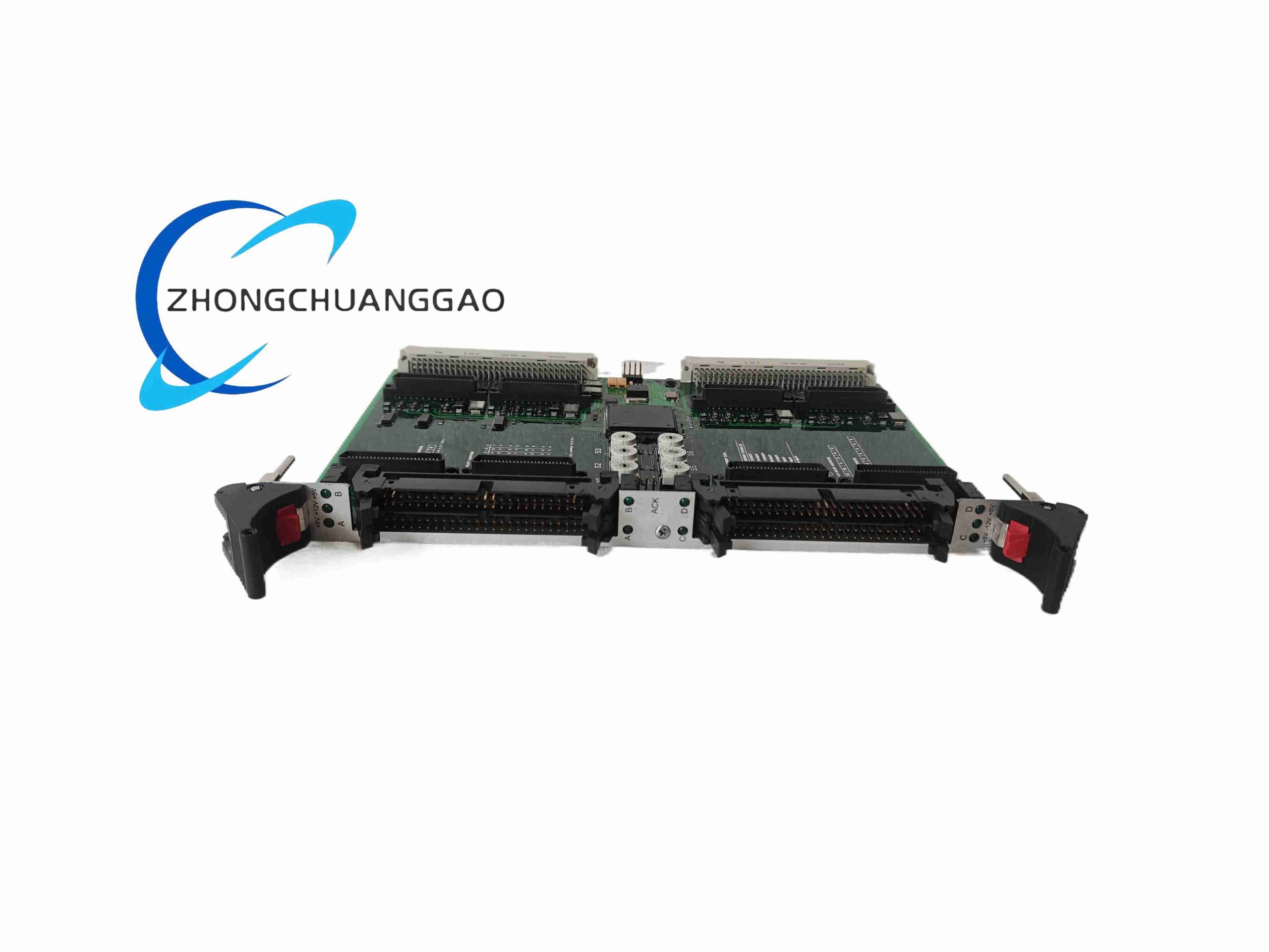
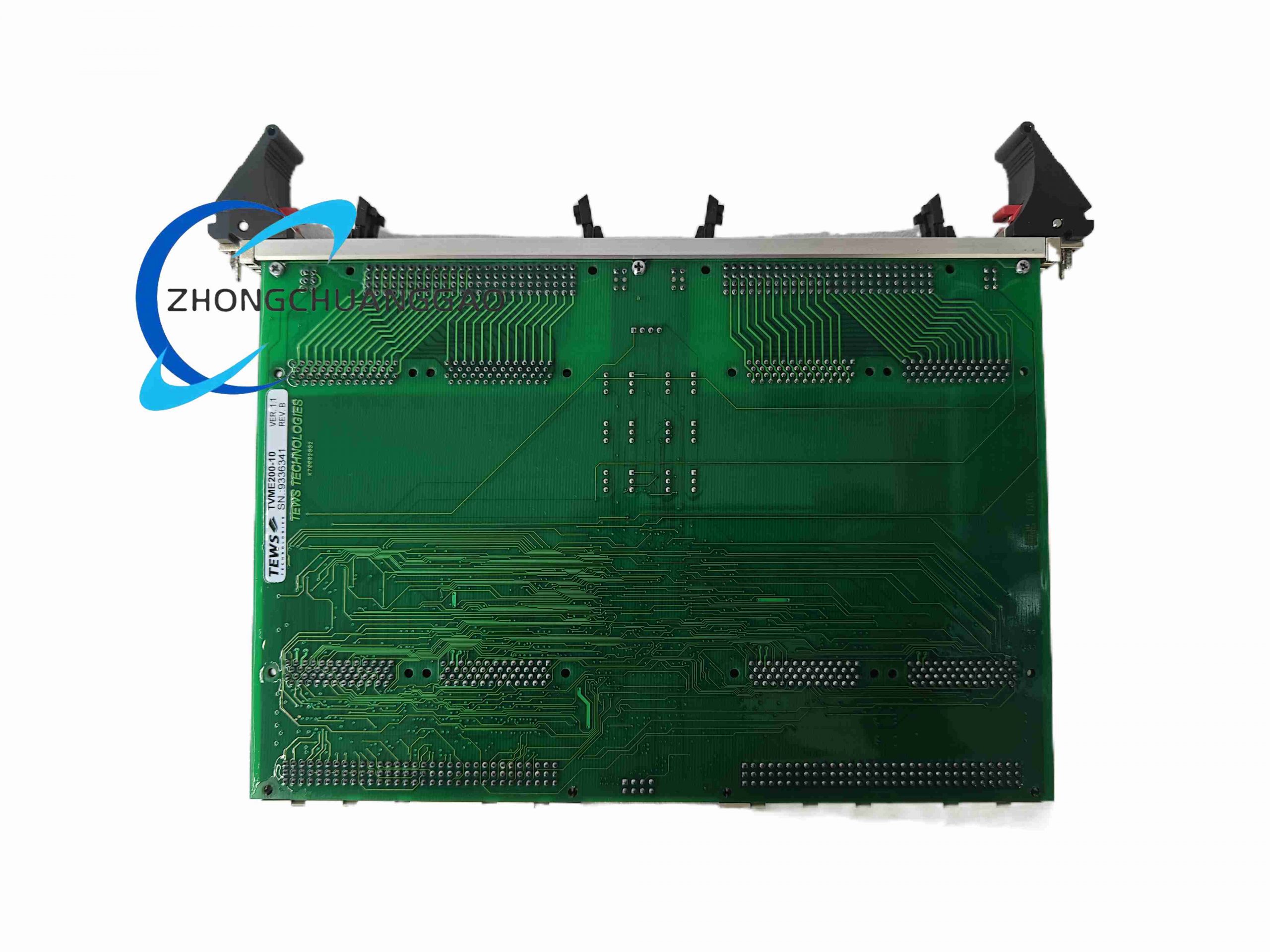
TVME200-10 is a high-performance VME standard industrial carrier board distributed under Honeywell industrial control product lines, developed by TEWS Technologies for rugged embedded industrial computing systems. It acts as a bridge between VME backplane bus and four independent IndustryPack (IP) peripheral modules, delivering regulated multi-rail power supply, interrupt routing, DMA signal distribution and status diagnostic functions for real-time industrial control hardware.

Description
Core Technical Performance Parameters
- Bus Standard: VME A24/A32 addressing space, VME64 compatible
- IP Slot Quantity: 4 independent IndustryPack slots (IP A/B/C/D)
- Memory Mapping: Each IP slot programmable memory range 32KB–2MB (A24); fixed 8MB extended memory per slot (A32)
- Interrupt Support: Full VME IRQ1–IRQ7 interrupt line routing, per-slot interrupt masking control
- Power Output Rails for IP Modules: +5V, ±12V isolated per slot, self-resettable fuse protection per channel
- Front Panel Status Indicator: 10 green LED indicators (4 IP access ACK LEDs, 6 power rail health LEDs)
- Input Operating Voltage: 220 VAC industrial mains power input
- Operating Frequency of Internal Power Conversion: 50 kHz high-frequency switching power circuit
- Operating Ambient Temperature Range: -60°C to +75°C continuous operation
- Protection Rating: IP30 for front panel assembly
- Physical Dimensions: 150mm × 100mm × 50mm
- Net Weight: 1.5 kg
- Certifications: CE, UL safety certification, RoHS II compliant
- Communication Interfaces: Dual RS-232 debug serial ports for system diagnosis
Function Features
- Independent power isolation and self-healing fuse protection for each IndustryPack slot, eliminating cross-slot short-circuit failure propagation
- Real-time visual hardware status monitoring via front-panel LED array; each ACK LED illuminates 200ms on every IP module read/write access
- Flexible interrupt configuration: software-selectable IRQ assignment for every peripheral slot to meet real-time control latency requirements
- Dual memory addressing architecture supporting both legacy A24 and high-capacity A32 VME bus equipment
- Integrated EMI filter circuit on all power and signal traces to suppress industrial field electromagnetic interference
- Hot-swap compatible signal routing logic for non-stop system maintenance of individual IP peripherals
- On-board diagnostic serial ports for fault log extraction and firmware parameter calibration without host controller shutdown
Working Principle
The board receives 220VAC mains input and converts it to stabilized +5V, +12V, -12V DC power rails via internal 50kHz high-frequency switching power supply circuits. Power rails are routed separately to four IP slots with independent fuses. The VME backplane bus address, data and interrupt signals are decoded by on-board FPGA logic, then mapped to each IndustryPack slot’s signal connector. When the host VME CPU executes read/write commands to an IP module, the corresponding ACK LED triggers, and interrupt signals from peripherals are multiplexed to the main VME interrupt bus. All power rail voltage levels are continuously sampled by monitoring circuits, triggering fault state flagging if voltage deviation exceeds ±5% rated value.
Material Composition & Structural Characteristics
- Main Circuit Board: 1.6mm thick FR4 high-temperature flame-retardant PCB, double-sided copper plating with heavy copper power traces for high current load
- Front Panel: Black anodized aluminum alloy metal frame, laser-etched function labels, dust-proof transparent polycarbonate LED window
- Power Components: Japanese industrial-grade electrolytic capacitors, high-temperature ferrite transformers, silicon carbide switching MOSFETs
- Connectors: Gold-plated VME backplane edge connector, tin-plated IndustryPack card edge sockets, screw-locked RS232 terminal blocks
- Internal Mechanical Structure: Reinforced PCB support ribs, shock-absorbing rubber cushion pads between PCB and aluminum front panel to resist 10–2000Hz vibration shock
Installation Requirements
- Standard 6U VME rack chassis mounting, vertical insertion into 19-inch industrial cabinet backplane slot
- Maintain minimum 20mm airflow clearance above and below the board for passive heat dissipation; forced air cooling required if ambient temperature exceeds 60°C
- Separate high-current power wiring and low-speed serial signal wiring by at least 15cm to reduce EMI crosstalk
- Secure all terminal block screws with torque of 0.8–1.0 N·m to prevent loose contact under vibration
- Ground the chassis aluminum front panel to cabinet protective earth via dedicated grounding wire with cross-section ≥1.5mm²
Application Scenarios
- Nuclear power plant DCS control cabinet embedded computing
- Railway locomotive signal and vehicle condition monitoring systems
- Aerospace ground test bench real-time data acquisition
- Heavy-duty marine vessel automation bus control systems
- Military ruggedized embedded industrial computing platforms
Operation & Maintenance Precautions
- Do not insert or remove IndustryPack modules while the board is powered; hot-swap only supported with dedicated isolated IP peripheral variants
- Avoid operation in environments with conductive metal dust, chemical corrosive gas or continuous condensation
- Perform annual inspection of front panel LED functionality and fuse integrity; replace self-resetting fuses if permanent power loss occurs on single slot
- Firmware upgrade via RS232 port only at ambient temperature between 10°C–40°C to prevent flash memory write failure
- Transport the module with anti-static foam packaging; all maintenance operations must be completed with certified ESD grounding wrist strap
-500x500.jpg)
-500x500.jpg)
Reviews
There are no reviews yet.