
Product Short Description
Product Brief
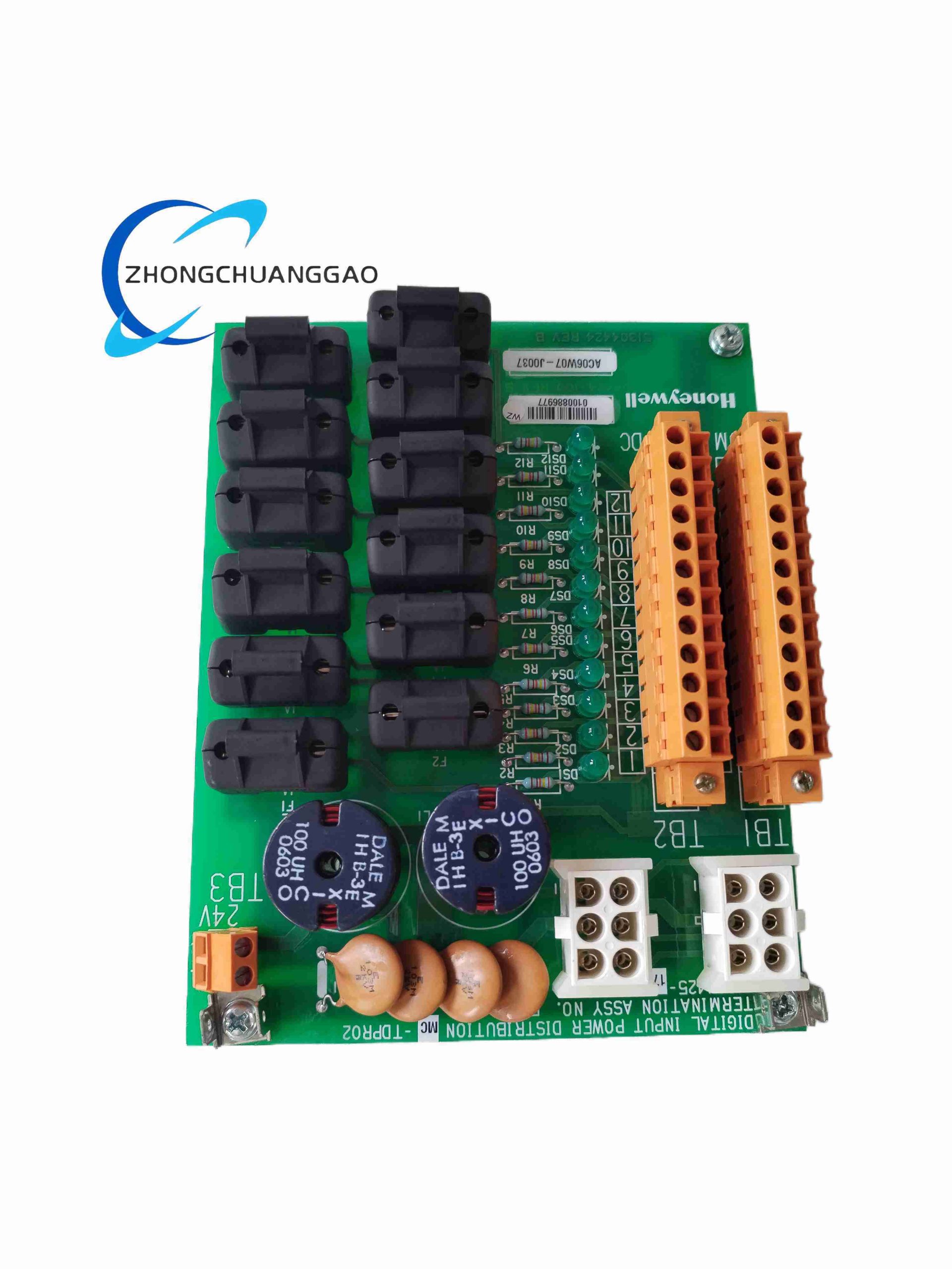
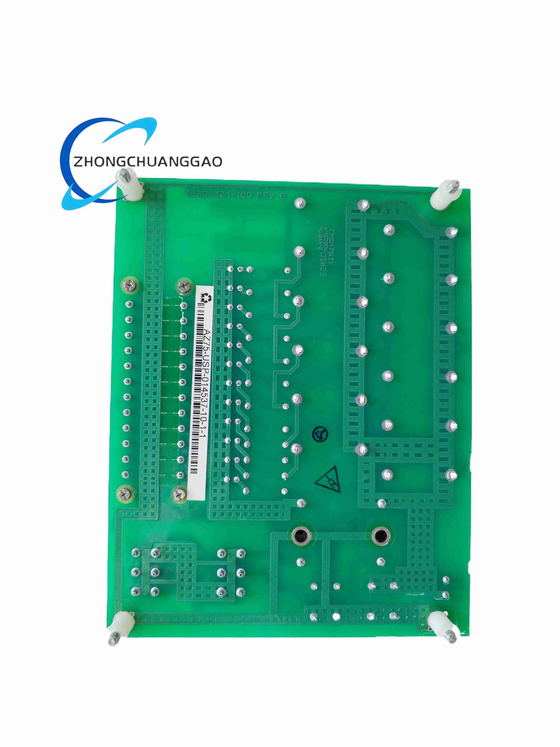
Rack-mounted high-speed pulse acquisition DCS module dedicated to flow meter pulse output sensors, captures frequency and totalization pulse signals from turbine flowmeters, vortex flow transmitters and positive displacement flow meters.
Model Series
Honeywell MC Series High-Speed Pulse & Frequency Measurement I/O Modules for Flow Process Automation
Description
Technical Specifications
- Pulse Input Channel Quantity: 4 isolated frequency measurement channels
- Input Pulse Frequency Range: 0 Hz – 100 kHz maximum high-speed pulse input
- Supported Pulse Signal Types: NPN open collector, 24 VDC square wave pulse, dry contact pulse
- Internal Pulse Totalizer Register: 32-bit non-volatile count storage per independent channel
- Channel Galvanic Isolation Rating: 1500 VAC isolation between field and backplane logic
- Operating Supply Voltage: 24 VDC backplane power (21.6 VDC – 26.4 VDC operating range)
- Operating Temperature Range: 0 °C to +60 °C
Functional Features
- Software configurable pulse scaling factor for engineering unit totalization (m³, kg, L, ton)
- Configurable pulse debounce filtering for mechanical contact pulse transmitters
- Non-volatile memory retention of flow totalization data during temporary power loss
- Hot-swappable backplane interface compatible with Honeywell standard DCS I/O rack
- Per-channel pulse loss diagnostic alarm for disconnected flow meter pulse wiring
Performance Parameters
- Pulse input low-level threshold: ≤ 6 VDC
- Pulse input high-level threshold: ≥ 18 VDC
- Minimum detectable pulse width: 5 μs for high-frequency flow pulse signals
- Totalizer register data retention duration: ≥ 10 years without external power supply
- Pulse measurement frequency accuracy: ≤ ±0.01% full frequency range
Material Composition
- Front panel housing: UL94 V-0 flame retardant black ABS plastic
- High-speed signal PCB: Low-capacitance FR4 fiberglass printed circuit board
- Pulse conditioning circuit: High-speed optocoupler isolation components
- Field wiring terminal block: Nickel-plated brass screw terminals, PA66 insulating housing
- Rack mounting assembly: Zinc-plated cold rolled steel anti-corrosion bracket frame
Structural Characteristics
- Half-width single-slot standard Honeywell DCS rack module footprint
- Detachable front screw terminal block for flow meter pulse signal wiring termination
- Individual channel LED pulse activity indicator and pulse fault status indicator
- Keyed polarized backplane connector preventing misalignment insertion into analog module slots
Working Principle
High-speed opto-isolation circuit receives square-wave pulse signals from field flow transmitters; internal counter logic accumulates pulse events into dedicated 32-bit non-volatile totalizer registers; on-board frequency calculation circuit converts pulse rate to instantaneous flow rate value; digital flow rate and totalization data packets transmitted to DCS controller over LCN backplane bus; continuous signal monitoring detects pulse signal absence and generates wire-break fault alarm flags.
Advantage Highlights
- Supports ultra-wide 0–100 kHz pulse frequency range compatible with all industrial flow meter pulse output standards
- On-board non-volatile totalizer eliminates flow data loss during cabinet power interruption events
- Galvanic channel isolation prevents electromagnetic interference distortion of low-amplitude pulse signals
- Built-in pulse scaling function directly outputs engineering unit flow values without additional controller math logic
- Hot-swap design enables module maintenance without full process control system shutdown
Applicable Industries
Oil & gas pipeline flow metering, chemical batch reactor feedstock flow monitoring, water treatment bulk flow measurement, natural gas custody transfer metering, food & beverage ingredient dosing flow tracking
Installation Requirements
- Install exclusively in Honeywell certified standard DCS I/O rack chassis slots
- Use shielded twisted-pair signal cable for all flow pulse field wiring connections
- Cable shielding single-point grounding only at control cabinet terminal strip
- Maintain minimum 10 mm vertical air clearance between adjacent rack modules for heat dissipation
- Field pulse wiring must be separated by minimum 30 cm distance from high-voltage AC power cabling
Usage Precautions
- Do not connect AC mains voltage signals to pulse input terminals; irreversible high-speed optocoupler damage occurs
- Mechanical contact pulse transmitters require appropriate software debounce configuration to avoid false pulse counting
- Disconnect all field flow meter wiring before removing module from rack for maintenance
- Avoid exposure of front terminal block to conductive dust or moisture inside control cabinet
- Execute totalizer register data backup prior to module replacement operations
-500x500.jpg)
Reviews
There are no reviews yet.