
Product Short Description
Product Overview
Honeywell single-channel analog signal isolation filter unit, dedicated to 4–20mA, 0–10V analog sensor signal anti-interference processing in DCS process control systems, isolates field equipment ground loop interference and high-frequency harmonic noise, stabilizes analog signal transmission accuracy.
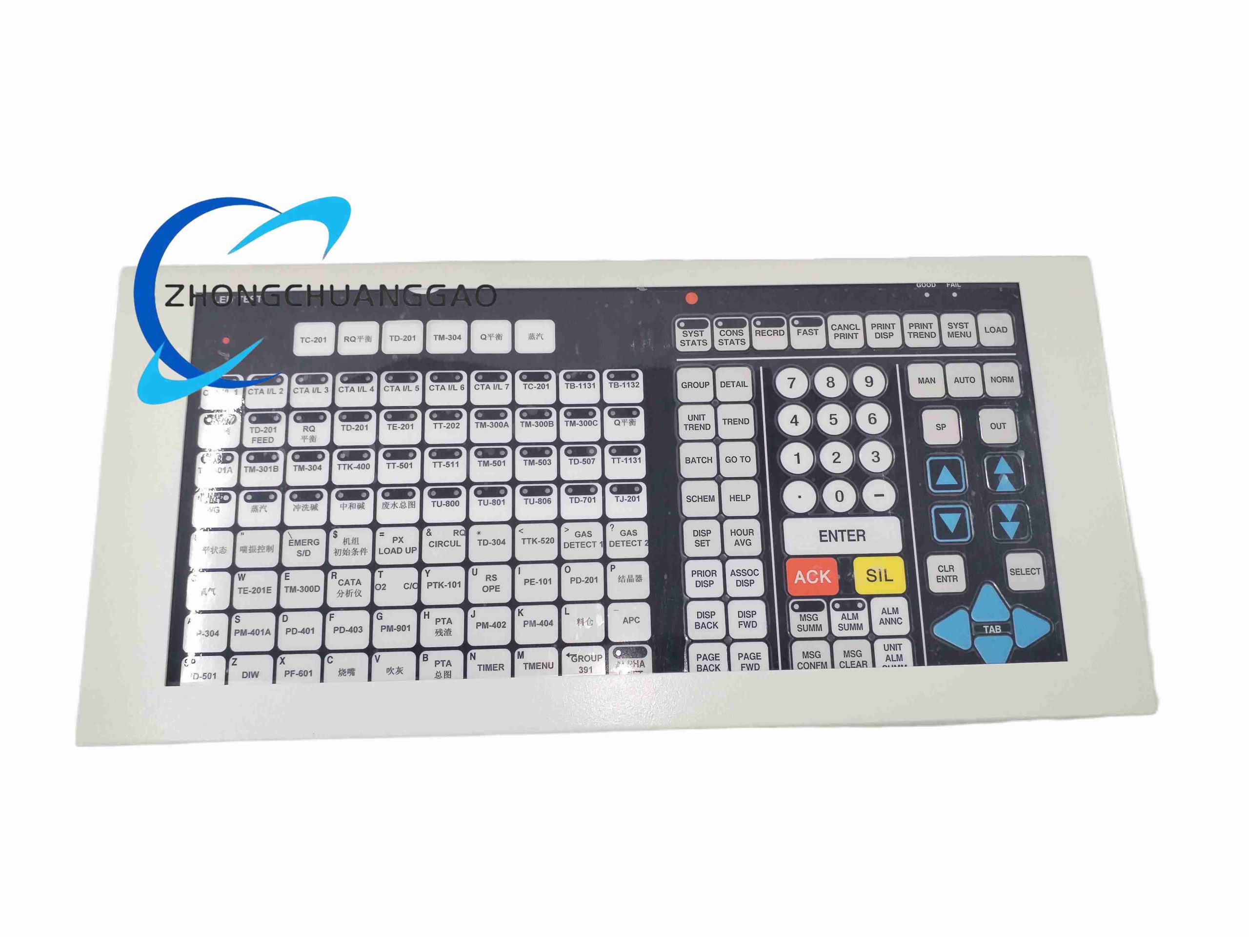
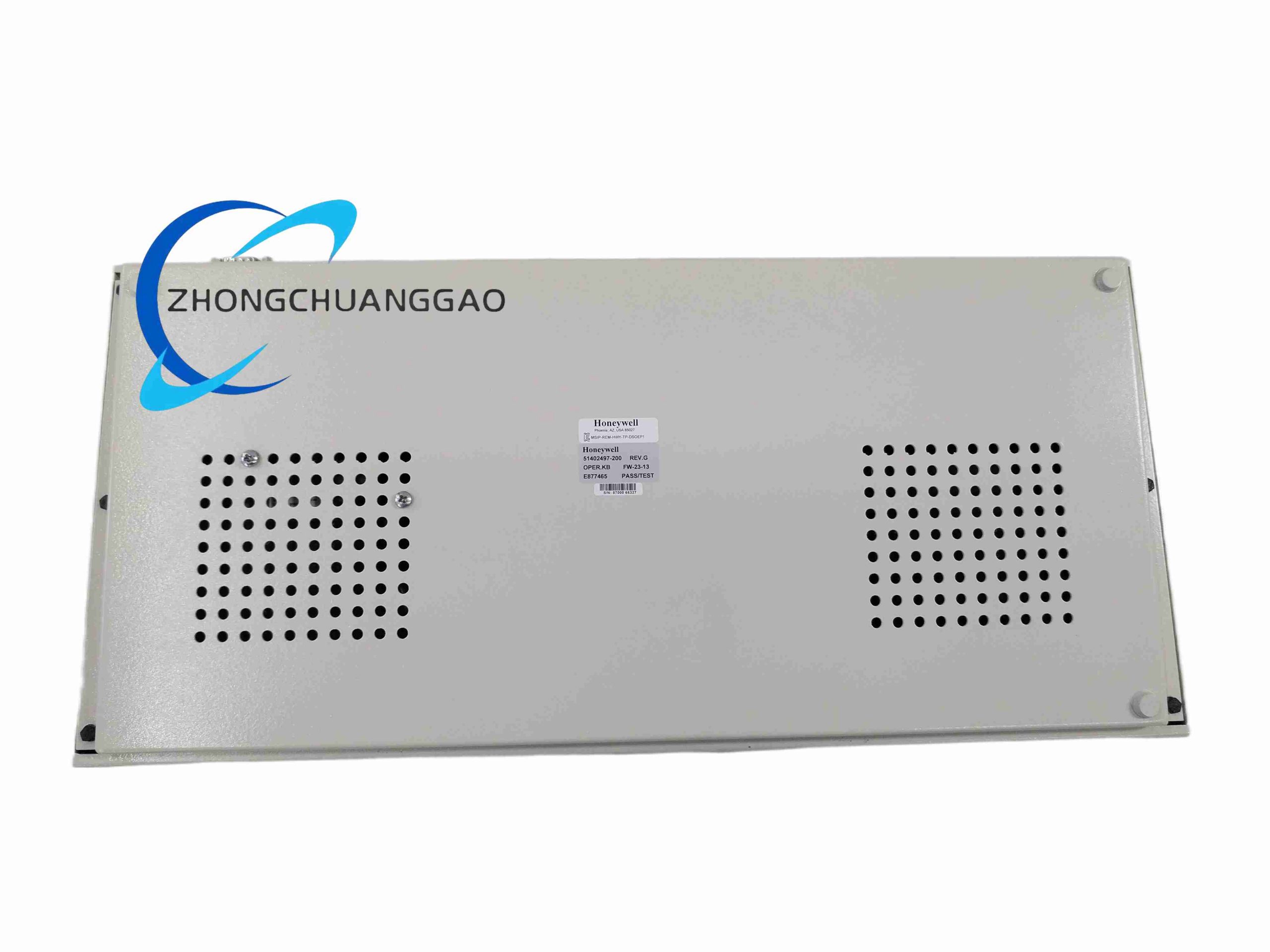
Description
Technical Specifications
- Signal input type: 4–20 mA current signal / 0–10 V voltage signal dual compatible
- Signal output type: Isolated 4–20 mA / 0–10 V matched with input signal
- Isolation voltage: 2500 V AC between input, output, power supply three ports
- Rated power supply: 24 V DC ±10%
- Signal filtering cutoff frequency: 23 Hz (-3dB) (FW-23 series model definition)
- Channel quantity: Single independent signal channel
- Operating temperature: -30°C ~ +70°C
- Mounting: Standard 35 mm DIN rail
- Dimensions: 96 mm × 22.5 mm × 110 mm
- Net weight: 0.06 kg
Function Features
- Three-port complete isolation (input / output / power) eliminates ground loop offset error caused by field and cabinet different ground potentials
- Built-in 23Hz low-pass analog filter to suppress motor frequency converter high-frequency interference spike noise
- Zero and span fine-tuning potentiometers on front panel for signal calibration without system shutdown
- Overvoltage, overcurrent reverse connection protection for input signal terminals
- Ultra-low signal transmission error, linearity error ≤0.05% full scale
- Compact 1 TE narrow width design, high cabinet wiring density
- No external auxiliary power required for passive signal input optional version
Application Scenarios
Petrochemical plant temperature/pressure transmitter signal isolation, chemical reactor flow meter signal filtering, power plant boiler thermocouple analog signal conditioning, water treatment plant online sensor noise suppression, food processing factory weighing sensor signal stabilization, mining underground instrument signal anti-interference transmission.
Performance Parameters
- Maximum transmission linearity error: 0.05% FS
- Temperature drift coefficient: ≤50 ppm/°C
- Signal response time constant: 120 ms
- Common mode interference rejection ratio: ≥120 dB at 50 Hz power frequency
- Long-term zero drift per year: ≤0.1% FS
- Insulation resistance between isolated ports: ≥1000 MΩ
Material Composition
- Housing: Flame retardant black PA66 plastic UL94 V-0
- Isolation core: Miniature high linearity isolation transformer
- Filter components: Metal film precision resistor, low temperature drift ceramic capacitor
- Adjustment potentiometer: Multi-turn metal ceramic precision trimming potentiometer
- Wiring terminal: Spring copper alloy push-in terminals
Structural Characteristics
Narrow single-channel DIN rail module, front panel left input terminals, right output terminals, middle zero/span adjustment potentiometers. Internal circuit layered isolation layout, input signal zone, isolation transformer zone, output signal zone separated by plastic insulation partitions to prevent crosstalk interference. Integrated metal shielding sheet between power circuit and signal circuit to reduce power supply noise coupling.
Working Principle
Field analog sensor signal enters input circuit, first passes 23Hz RC low-pass filter to filter high-frequency industrial noise spikes. Processed signal drives isolation transformer primary winding; secondary winding transmits isolated signal without ground loop conduction. Precision operational amplifier circuit converts isolated weak signal back to standard 4–20mA/0–10V analog output signal for DCS system AI module collection. Front multi-turn potentiometers adjust zero offset and full-scale span to compensate signal transmission loss and sensor drift. Three-port isolation transformer cuts off ground loop current path to eliminate signal offset deviation.
Installation Requirements
- Mount on DIN rail close to field signal cable inlet to shorten unfiltered raw signal wiring length
- Separate analog signal module wiring and high-power frequency converter power cables with minimum 25 mm spacing
- Signal cable use shielded twisted pair, shield grounding only at DCS cabinet end, field side shield floating
- Leave 5 mm gap between adjacent FW-23-13 modules for heat dissipation
- Power supply wiring use independent 24V DC control power, avoid sharing with high inductive loads
Use & Maintenance Precautions
- Do not input signal voltage exceeding 30 V DC, will damage internal input operational amplifier
- Re-calibrate zero and span every 6 months of continuous operation, or after sensor replacement
- Avoid installing module near vibration sources such as fans, pumps; vibration causes potentiometer parameter drift
- Do not use strong solvent to wipe plastic housing, will damage surface silk-screen marking
- Regularly check terminal wiring tightness, loose wires generate signal fluctuation noise
- Store spare modules in low humidity environment to prevent internal circuit board capacitance leakage
-500x500.jpg)

Reviews
There are no reviews yet.