Product Short Description
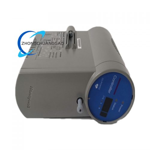
Honeywell 05701-A-0351 is a solid-state digital electronic speed governor manufactured by Honeywell International Inc. (headquartered in Charlotte, North Carolina, USA). This device serves as the primary speed control system for industrial gas turbines, steam turbines, diesel engines, and compressor drive trains ranging from 1 MW to 150+ MW. It replaces the legacy analog 505/505E governors and provides full digital control of engine speed, load sharing, synchronizing, acceleration/deceleration ramping, and comprehensive turbine protection.
Description
Model Series
Honeywell 05701 Series Digital Electronic Governors
Related models in the 05701 series include:
- Honeywell 05701-A-0001 — Base 05701 governor, single speed input, no communication
- Honeywell 05701-A-0101 — 05701 with dual speed input (redundant)
- Honeywell 05701-A-0201 — 05701 with load control and synchronization
- Honeywell 05701-A-0351 — 05701 with isolated speed input, fuel limiting, RS-485, programmable ramps (this model)
- Honeywell 05701-B-0001 — 05701 with PMG input variant
- Honeywell 05704 — Next-generation Experion PKS-integrated turbine controller (successor platform)
- Honeywell 505E — Legacy analog electronic governor (replaced by 05701 series)
- Honeywell 505F — Legacy analog governor with fuel limiter (replaced by 05701 series)
Manufacturer
Honeywell International Inc.
Honeywell Process Solutions
Address: 115 Tabor Road, Morris Plains, NJ 07950, USA
Parent Company: Honeywell International Inc., 901 Freeport Parkway, Morris Township, NJ 07962, USA
Technical Specifications
| Parameter | Specification |
|---|---|
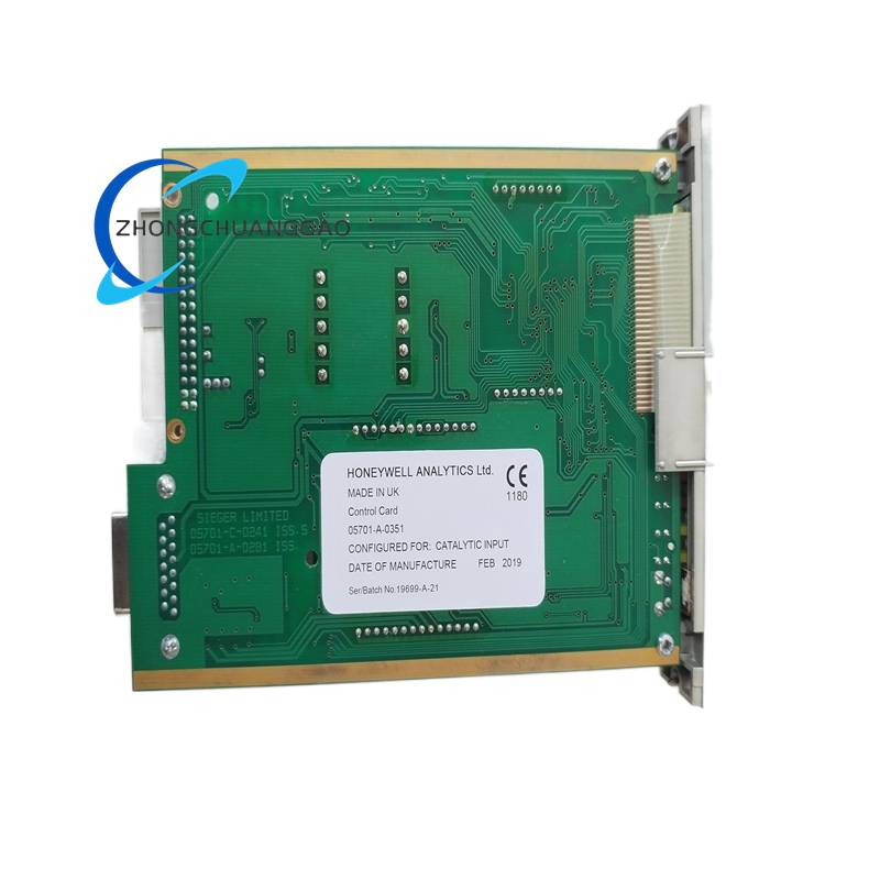
| Part Number | 05701-A-0351 |
| Controller Type | Digital Microprocessor-Based Electronic Speed Governor |
| Speed Input | Isolated MPU (Magnetic Pickup Unit), 10 VAC to 240 VAC, 10 Hz to 10 kHz |
| Speed Input (Alternate) | PMG (Permanent Magnet Generator), 400 Hz to 1600 Hz, 15 VAC to 120 VAC |
| Speed Range | 0 to 110% of rated speed (50 Hz or 60 Hz base) |
| Speed Accuracy (Steady State) | ±0.025% of setpoint |
| Speed Accuracy (Transient) | ±0.1% during 10% to 100% load step |
| Speed Droop Range | 0% to 10% adjustable (isochronous to 10% droop) |
| Load Control Range | 0% to 100% of rated load |
| Synchronizing | Auto-synchronization with voltage, frequency, and phase matching |
| Control Output (Fuel) | 4 to 20 mA (fuel servo), 0 to 10 VDC (auxiliary), relay contacts (alarm/trip) |
| Analog Inputs | 4 to 20 mA (×4 channels), 0 to 10 VDC (×2 channels), RTD Pt100 (×2 channels), TC (Type K/J, ×2 channels) |
| Digital Inputs | 24 VDC, opto-isolated (×16 channels, wet/dry contact selectable) |
| Digital Outputs | 24 VDC, transistor (×12 channels), relay (×6 channels, 5 A @ 250 VAC) |
| Communication Interfaces | RS-485 (Modbus RTU), RS-232, Ethernet (optional module via expansion) |
| Power Supply | 24 VDC nominal (18 VDC to 32 VDC range), 8 W maximum |
| Operating Temperature Range | -20°C to +60°C (-4°F to +140°F) |
| Storage Temperature Range | -40°C to +85°C (-40°F to +185°F) |
| Humidity Range | 5% to 95% RH, non-condensing |
| Altitude | Up to 3,000 m (10,000 ft) above sea level (derate above 1,000 m) |
| Vibration Tolerance | Per IEC 60068-2-6, 5g RMS, 10 Hz to 200 Hz |
| Shock Tolerance | Per IEC 60068-2-27, 15g, 11 ms half-sine |
| EMC Compliance | IEC 61000-6-2 (Industrial), IEC 61000-6-4 (Emission), IEC 61000-4-2 (ESD ±8 kV contact, ±15 kV air) |
| Enclosure Rating | IP54 (front panel), NEMA 4X (when panel-mounted with gasket) |
| Dimensions (W × H × D) | Approximately 146 mm × 197 mm × 120 mm (5.75 in × 7.75 in × 4.75 in) |
| Weight | Approximately 1.7 kg (3.75 lbs) |
| Certifications | CE, UL 508, CSA C22.2 No. 142, ATEX Zone 2 (optional), DNV GL (marine) |
| Compliance Standards | ISO 8528-5, ISO 8528-9, IEC 60034, IEEE 1547, NFPA 85, IEC 61508 (SIL 2 with safety module) |
| Safety Integrity Level | SIL 2 per IEC 61508 (with optional Honeywell safety I/O module) |
Functional Features
- Isolated MPU speed input — accepts magnetic pickup signal from 10 VAC to 240 VAC with galvanic isolation, eliminating ground loop errors common in turbine installations
- Isochronous and droop speed control — switchable between 0% droop (isochronous) and 10% droop for single-machine or parallel operation without hardware changes
- Automatic load sharing — when multiple 05701 governors operate in parallel, each unit automatically adjusts fuel to maintain equal load distribution within ±0.5% via RS-485 peer-to-peer communication
- Auto-synchronization — matches voltage magnitude, frequency, and phase angle before closing the breaker, with adjustable synchronizing time window of 0.1 s to 60 s
- Programmable fuel limiting — hard fuel limit and soft fuel limit functions with configurable acceleration and deceleration rates from 0.1%/s to 100%/s
- Engine and turbine protection — includes overspeed trip, underspeed trip, overtemperature trip, low oil pressure trip, high exhaust temperature trip, reverse power trip, loss of load trip, and vibration trip with fully configurable setpoints and time delays
- Governor mode switching — supports Speed Control, Load Control, Isochronous, and Droop modes selectable via front panel, remote signal, or Modbus command
- Remote monitoring and control — RS-485 Modbus RTU and RS-232 interfaces enable full remote access to speed, load, fuel position, droop setting, and all alarm/trip status from a SCADA system or HMI
- Event logging — internal non-volatile EEPROM stores the last 512 events with millisecond timestamps for post-event analysis
- Load transducer calibration — built-in two-point calibration routine for 4 to 20 mA load inputs with automatic sensor fault detection (open circuit, short circuit, out-of-range, drift)
- Black start capability — supports automatic black start sequencing for gas turbines when commanded via remote signal or Modbus
Performance Parameters
| Parameter | Specification |
|---|---|
| Speed Control Accuracy (Steady State) | ±0.025% of setpoint |
| Speed Control Accuracy (Transient) | ±0.1% during 10% to 100% load step change |
| Load Control Accuracy | ±0.5% of setpoint |
| Frequency Regulation (Isochronous) | ±0.005 Hz at 50 Hz / ±0.006 Hz at 60 Hz |
| Response Time (Speed) | < 80 ms for 10% load step change |
| Analog Input Resolution | 16-bit ADC, 0.0015% of full scale, 10 ms sampling rate |
| Analog Output Resolution | 12-bit DAC, 0.024% of full scale |
| Communication Baud Rate | 9600, 19200, 38400, 57600, 115200 bps (configurable via front panel or Modbus) |
| Mean Time Between Failures (MTBF) | > 200,000 hours (per MIL-HDBK-217F) |
| Software Update | Field-upgradeable via RS-232, RS-485, or USB (USB adapter optional) |
| SIL Rating (with safety module) | SIL 2 per IEC 61508, PFH < 1 × 10⁻⁷ /hour |
| Calibration Interval | 12 months recommended for speed and load inputs |
| Droop Accuracy | ±0.05% of configured droop setting |
| Load Sharing Accuracy (2 to 8 units) | ±0.5% of total load |
| Ramp Rate Accuracy | ±2% of programmed ramp rate |
Material Composition
| Component | Material |
|---|---|
| Enclosure | Die-cast aluminum alloy (ADC12), powder-coated, RAL 7035 (light gray) |
| Front Panel | 1.6 mm anodized aluminum, laser-etched legend, UV-resistant ink |
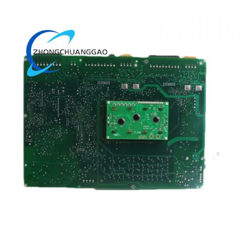
| PCB Substrate | FR-4 epoxy glass laminate, 6-layer, Tg ≥ 170°C, lead-free HASL finish |
| Connector Housings | Glass-fiber reinforced polyamide (PA66-GF30), UL 94 V-0 rated |
| Connector Contacts | Phosphor bronze, gold-plated (30 μin Au over 100 μin Ni) |
| Wire Terminals | Tin-plated copper alloy, spring-clamp type, 14 AWG to 24 AWG |
| Display | LED backlit LCD, 20 × 2 characters, wide viewing angle, operating range -20°C to +60°C |
| Potentiometers | Cermet trim potentiometer, sealed, 10-turn, 5 kΩ |
| Seals and Gaskets | Silicone rubber, 70 Shore A durometer, UV-stabilized |
| Conformal Coating | Acrylic conformal coating (per IPC-CC-830B, Class 3) |
| Mounting Hardware | Stainless steel 304, passivated, zinc-plated screws |
| Internal Shielding | Mu-metal shield around analog signal conditioning circuitry, copper tape shield around digital section |
| Fuses | 5 × 20 mm glass tube fuses, 250 mA (logic), 2 A (power), 5 A (output) |
| Backup Battery | CR2032 lithium coin cell for real-time clock and event log retention |
| Isolation Transformers | Custom wound toroidal core, 1:1 ratio, 1500 VDC isolation rating |
Structural Characteristics
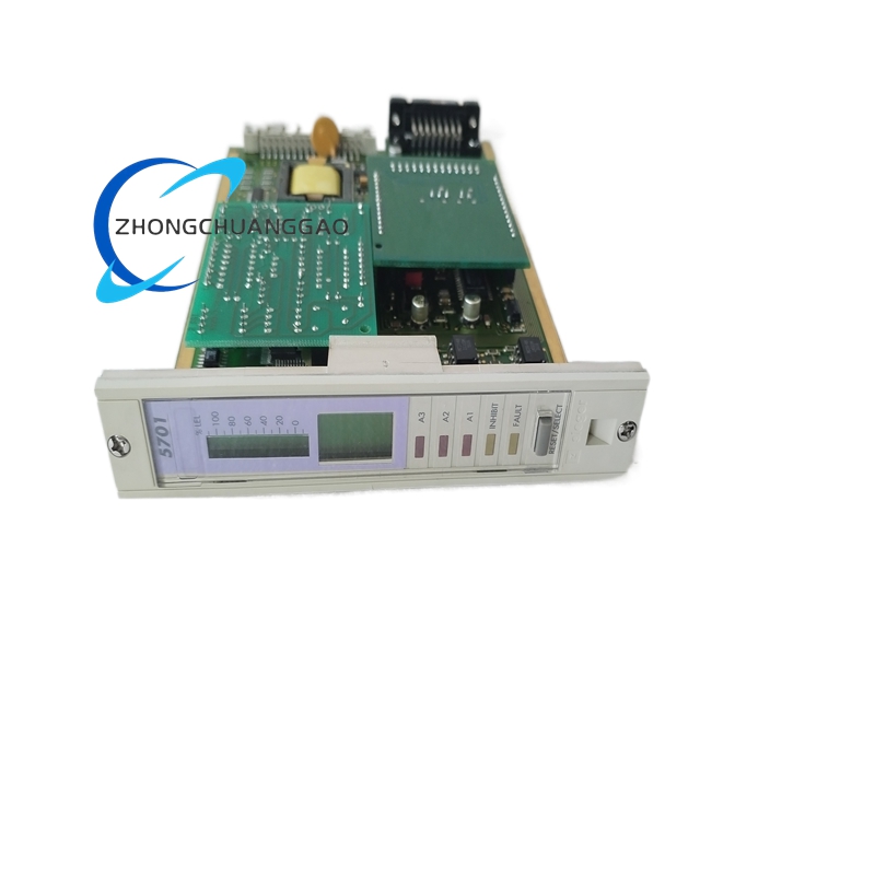
- Form Factor: DIN rail or panel-mountable governor with integrated front panel interface, compatible with standard 35 mm DIN rail (EN 60715)
- Front Panel Layout:
- 20 × 2 character LCD display — shows speed, load, fuel position, droop setting, mode, alarm status, and event counter
- 5 × push-button navigation keys — menu navigation, up/down, enter, escape, mode select
- 2 × rotary potentiometers — speed setpoint and speed droop adjustment (10-turn, sealed)
- 8 × LED indicators — power, run, alarm, trip, sync, communication, load share active, fault
- 2 × mini-DIN connectors — RS-485 and RS-232 communication ports
- 1 × DB-25 connector — analog I/O and digital I/O breakout
- 1 × USB Type-B connector (optional) — firmware update and configuration download
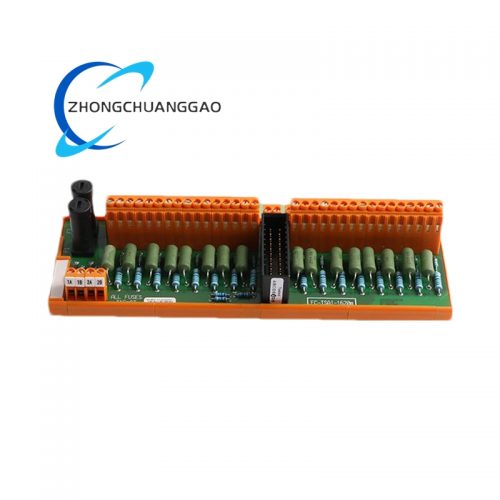
- Rear Panel:
- 2 × 6-pin terminal blocks — speed input (MPU isolated or PMG)
- 1 × 8-pin terminal block — load input (4 to 20 mA, ×2 channels)
- 1 × 8-pin terminal block — fuel servo output (4 to 20 mA)
- 2 × 6-pin terminal blocks — digital inputs (×16 channels total, wet/dry selectable)
- 2 × 8-pin terminal blocks — relay outputs (×6 channels total, 5 A @ 250 VAC)
- 1 × 4-pin terminal block — 24 VDC power input
- 1 × 6-pin terminal block — RTD inputs (Pt100, ×2 channels)
- 1 × 4-pin terminal block — TC inputs (Type K/J, ×2 channels)
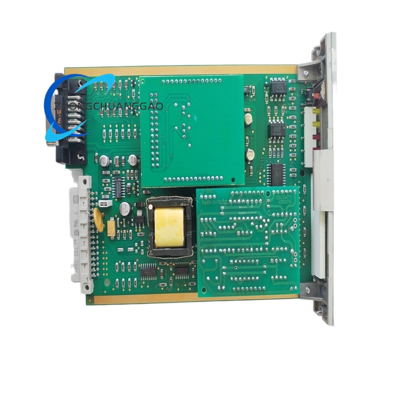
- Internal Layout:
- Main processor board — mounted vertically on the left side, 6-layer PCB with isolated analog and digital ground planes, separate power planes for logic and I/O
- Power supply module — isolated DC-DC converter (24 VDC to 5 VDC, 3.3 VDC, ±12 VDC), mounted on the right side with EMI filter
- Analog I/O board — removable plug-in module with 16-bit ADC and 12-bit DAC, fully shielded compartment with mu-metal enclosure
- Digital I/O board — removable plug-in module with opto-isolated inputs (24 VDC, 3 mA) and transistor/relay outputs
- Communication module — removable RS-485/RS-232/Ethernet board with galvanic isolation (1500 VDC)
- Isolation barrier — optical isolation (6-channel) and transformer isolation (2-channel) between speed input and logic circuitry
Working Principle
- Speed Sensing: The isolated MPU (Magnetic Pickup Unit) mounted on the turbine shaft generates an AC voltage whose frequency is directly proportional to turbine speed. The 05701-A-0351 accepts this signal on the isolated speed input terminals and measures frequency from 10 Hz to 10 kHz through an optical isolation barrier
- Frequency-to-Speed Conversion: The internal microprocessor converts the MPU frequency to turbine speed in RPM or Hz using the formula: Speed (RPM) = (Frequency × 60) / Number of MPU teeth
- Error Calculation: The measured speed is compared against the speed setpoint (entered via front panel potentiometer or remote Modbus command). The difference is the speed error signal
- PID Control: A digital Proportional-Integral-Derivative (PID) controller with auto-tune capability processes the speed error and generates a fuel demand signal (4 to 20 mA) proportional to the required fuel flow change
- Fuel Servo Actuation: The 4 to 20 mA signal drives the fuel control valve servo motor, which adjusts the fuel rack position to increase or decrease fuel flow
- Droop Compensation: In droop mode, the speed setpoint is automatically reduced as load increases according to the configured droop percentage (0% to 10%), enabling stable parallel operation of multiple turbines
- Load Sharing (Parallel Mode): In parallel configurations, each 05701 governor communicates load data via RS-485 Modbus RTU. Each unit compares its own load against the average load of all units and adjusts its fuel output to achieve equal sharing within ±0.5%
- Synchronization: During auto-sync, the governor compares the generator voltage frequency and phase against the bus voltage. When all three parameters (voltage, frequency, phase) are within the configured window, the governor sends a breaker close command via a relay output
- Protection Monitoring: The governor continuously monitors all protection inputs (overspeed, underspeed, overtemperature, low oil pressure, high exhaust temperature, reverse power, loss of load, vibration). If any parameter exceeds its trip setpoint, the governor immediately commands a fuel cut via relay output and sends a trip alarm via Modbus
- Event Recording: Every state change, alarm, trip, and operator action is timestamped and stored in non-volatile EEPROM for post-event analysis. The log retains the last 512 events
- Black Start Sequence: Upon receiving a black start command, the governor executes a predefined ramp sequence: idle speed hold for 60 seconds, ramp to synchronization speed at 1%/s, synchronize, close breaker, ramp to no-load at 2%/s, then ramp to target load at programmed rate
Advantages and Highlights
- Galvanically isolated speed input — eliminates ground loop errors that plague non-isolated governors in large turbine installations with multiple ground paths
- Digital PID control with auto-tune — achieves ±0.025% speed accuracy without manual PID tuning, superior to legacy analog governors
- Automatic load sharing ±0.5% — peer-to-peer RS-485 communication enables precise load balancing without a master controller
- Programmable fuel limiting with smooth ramps — protects turbine from thermal shock during startup, shutdown, and load transfer
- Event logging with 512 entries — comprehensive post-event diagnostic capability eliminates guesswork in fault analysis
- Field-upgradeable firmware — software updates performed via RS-232, RS-485, or USB without removing the governor from the panel
- Wide operating temperature -20°C to +60°C — suitable for outdoor installations in arctic, desert, and tropical environments without climate control
- SIL 2 safety rating — with optional Honeywell safety I/O module, the governor meets IEC 61508 SIL 2 for safety-critical turbine protection
- Drop-in replacement for 505E — identical footprint and wiring compatibility with Honeywell analog 505E governors simplifies migration
- Modbus RTU standard protocol — seamless integration with any SCADA, DCS, PLC, or HMI system without proprietary gateway hardware
- IP54 front panel rating — dust and splash-proof front panel suitable for harsh industrial environments
- 15-year product lifecycle guarantee — Honeywell guarantees minimum 15-year availability for the 05701 series
Applicable Industries
| Industry | Application |
|---|---|
| Oil and Gas | Gas turbine-driven compressors, generator sets for remote well sites, pipeline pump stations, LNG liquefaction plants |
| Power Generation | Industrial gas turbine gensets, steam turbine gensets, combined heat and power (CHP) plants, peak shaving systems |
| Marine | Ship propulsion gas turbines, marine generator sets, offshore platform power systems, naval vessel auxiliary power |
| Mining | Gas turbine generator sets for remote mining operations, load sharing among multiple gensets |
| Data Centers | Backup gas turbine generator sets for critical infrastructure, automatic load ramp control |
| Manufacturing | Cogeneration plants, industrial process power, load management for multiple parallel gensets |
| Telecommunications | Backup power for cell towers, switching stations, data centers with automatic load sharing |
| Military and Defense | Mobile tactical generator sets, naval vessel propulsion and auxiliary power, field hospital gensets |
| Renewable Energy | Biogas engine gensets, waste-to-energy plants, solar-gas hybrid systems |
| Rail and Transit | Gas turbine locomotive auxiliary power, rail yard gensets, station backup power |
| Hospitals and Healthcare | Critical backup power with automatic load management and seamless transfer |
| Commercial Buildings | Standby generator load control for large commercial facilities with multiple gensets |
| Pulp and Paper | Steam turbine drive control, black coal boiler feedwater pump control |
| Chemical and Petrochemical | Gas turbine-driven compressors, critical process power backup |
Installation Requirements
- Installation must be performed by qualified electrical technicians trained in Honeywell governor wiring and NEC/IEC standards
- The governor must be mounted on a vertical DIN rail (35 mm, EN 60715) or panel-mounted using the four corner mounting holes with M4 screws
- Power supply wiring: Connect 24 VDC (18–32 VDC) to the rear panel terminal block with minimum 14 AWG copper wire. Do not exceed 32 VDC under any condition
- Speed input wiring (MPU isolated): Connect magnetic pickup output to the rear panel isolated speed terminals using shielded twisted pair cable. Shield ground must connect to chassis ground at one end only (governor end). The isolation barrier provides 1500 VDC galvanic isolation
- Speed input wiring (PMG): Connect PMG output (A+, A−, B+, B−) using shielded twisted pair cable. Shield ground connects to chassis ground at one end only
- Load input wiring: Connect 4 to 20 mA load transducer output using shielded twisted pair cable. The transducer loop resistance must not exceed 750 Ω
- Fuel servo wiring: Connect the 4 to 20 mA fuel output to the fuel servo motor using shielded cable. The servo motor impedance must be 250 Ω to 750 Ω
- Grounding: The governor chassis must be connected to equipment ground with a wire size no smaller than 10 AWG copper. Ground resistance must be < 5 Ω
- Ambient temperature: Ensure the installation location maintains temperature within -20°C to +60°C. Do not install in direct sunlight or near heat sources exceeding 70°C
- Ventilation: Provide minimum 10 cm (4 inches) clearance above and below the governor for natural convection cooling. Do not stack governors directly on top of each other
- Cable routing: Keep signal cables (speed, load, analog I/O) separated from power cables by a minimum of 15 cm (6 inches) to prevent electromagnetic interference
- RS-485 wiring: Use shielded twisted pair cable (120 Ω characteristic impedance) with termination resistors (120 Ω) at both ends of the bus for installations exceeding 10 meters
- After installation: Perform a full functional test using the front panel menu to verify speed sensing, fuel output, droop setting, protection functions, and communication before energizing the turbine
Usage Precautions
- Do not exceed 32 VDC on the power input — overvoltage permanently damages the internal isolated DC-DC converter
- Do not connect MPU input when the turbine is rotating above 120% speed — overfrequency input damages the speed measurement circuitry
- Do not short the 4 to 20 mA fuel output — a short circuit causes the fuel servo to drive to full stroke, resulting in turbine overspeed and potential catastrophic failure
- Do not disconnect the isolated speed signal while the turbine is running — loss of speed signal causes the governor to trip on underspeed protection within 2 seconds
- Do not modify the firmware without Honeywell authorization — unofficial firmware changes void the certification, warranty, and SIL rating
- Do not operate the governor in environments with corrosive gases (H₂S, Cl₂, SO₂) without an NEMA 4X enclosure — corrosion degrades terminal contacts and PCB traces within months
- Do not cover the front panel ventilation slots — blocked airflow causes internal temperature to exceed the +60°C limit, leading to thermal shutdown and potential component damage
- Do not use the relay outputs to switch inductive loads exceeding 5 A without a snubber circuit (RC 100 Ω / 0.1 μF) — inductive kickback damages the relay contacts and causes EMI
- Calibrate the speed input (MPU/PMG) annually — MPU air gap and PMG output drift over time, affecting speed measurement accuracy beyond the ±0.025% specification
- Replace the CR2032 backup battery every 3 years — battery failure causes loss of real-time clock and event log timestamps during power outages
- Do not exceed the maximum of 16 digital inputs and 12 digital outputs — overloading the I/O bus causes communication errors and unreliable operation
- Recalibrate the load transducer input after any mechanical disturbance — vibration or shock can shift the transducer mounting, affecting load measurement accuracy
- Store spare units in a dry environment at 5% to 85% RH, temperature 10°C to 35°C — moisture ingress causes PCB corrosion and conformal coating delamination
- Replace the governor at end of lifecycle (15 years from manufacture date) — component obsolescence, capacitor aging, and solder joint fatigue degrade long-term reliability beyond this period
- Verify RS-485 termination — for bus lengths exceeding 10 meters, 120 Ω termination resistors must be installed at both ends of the bus. Missing termination causes signal reflections and communication errors
Part Number Decoding
| Segment | Meaning |
|---|---|
| 05701 | Product family — Digital Electronic Governor, 05700 Series |
| A | Platform code — Isolated MPU speed input, standard configuration |
| 0351 | Configuration code — Fuel limiting, RS-485, programmable ramps, 16 DI / 12 DO, event logging |
| REV | Hardware platform revision (varies by production lot) |
Document Reference
- Manufacturer: Honeywell International Inc., 115 Tabor Road, Morris Plains, NJ 07950, USA
- Parent Company: Honeywell International Inc., 901 Freeport Parkway, Morris Township, NJ 07962, USA
- Technical Manual: Honeywell Publication 057010-0100-000 (05701 Governor Installation and Operation Manual)
- Application Guide: Honeywell Publication 057010-0200-000 (05701 Load Sharing Configuration Guide)
- Applicable Standards: ISO 8528-5, ISO 8528-9, IEC 60034, IEEE 1547, NFPA 85, IEC 61508, IEC 61000-6-2, IEC 61000-6-4, DNV GL (marine)
- Communication Protocol: Modbus RTU, Slave Address configurable (default 1), Baud Rate 9600–115200 bps
- Replacement Part Numbers:
- 05701-A-0001 — Base governor (no communication, no fuel limit)
- 05701-A-0101 — Governor with dual speed input (redundant)
- 05701-A-0201 — Governor with load control and synchronization
- 05704-001 — Next-generation Experion PKS-integrated turbine controller (recommended successor)
- 505E — Legacy analog governor (replaced by 05701 series)
- SIL Rating: SIL 2 per IEC 61508 (with Honeywell safety I/O module 05701-SIL)
- Firmware Version: Field-upgradeable, current version: 5.2.x (verify at time of installation)
- Spare Parts:
- 05701-A-0010 — Replacement front panel assembly
- 05701-A-0020 — Replacement main processor board
- 05701-A-0030 — Replacement power supply module
- 05701-A-0040 — Replacement analog I/O board
- 05701-A-0050 — Replacement digital I/O board
- 05701-A-0060 — Replacement communication module
Reviews
There are no reviews yet.