
Product Short Description
Product Brief Introduction
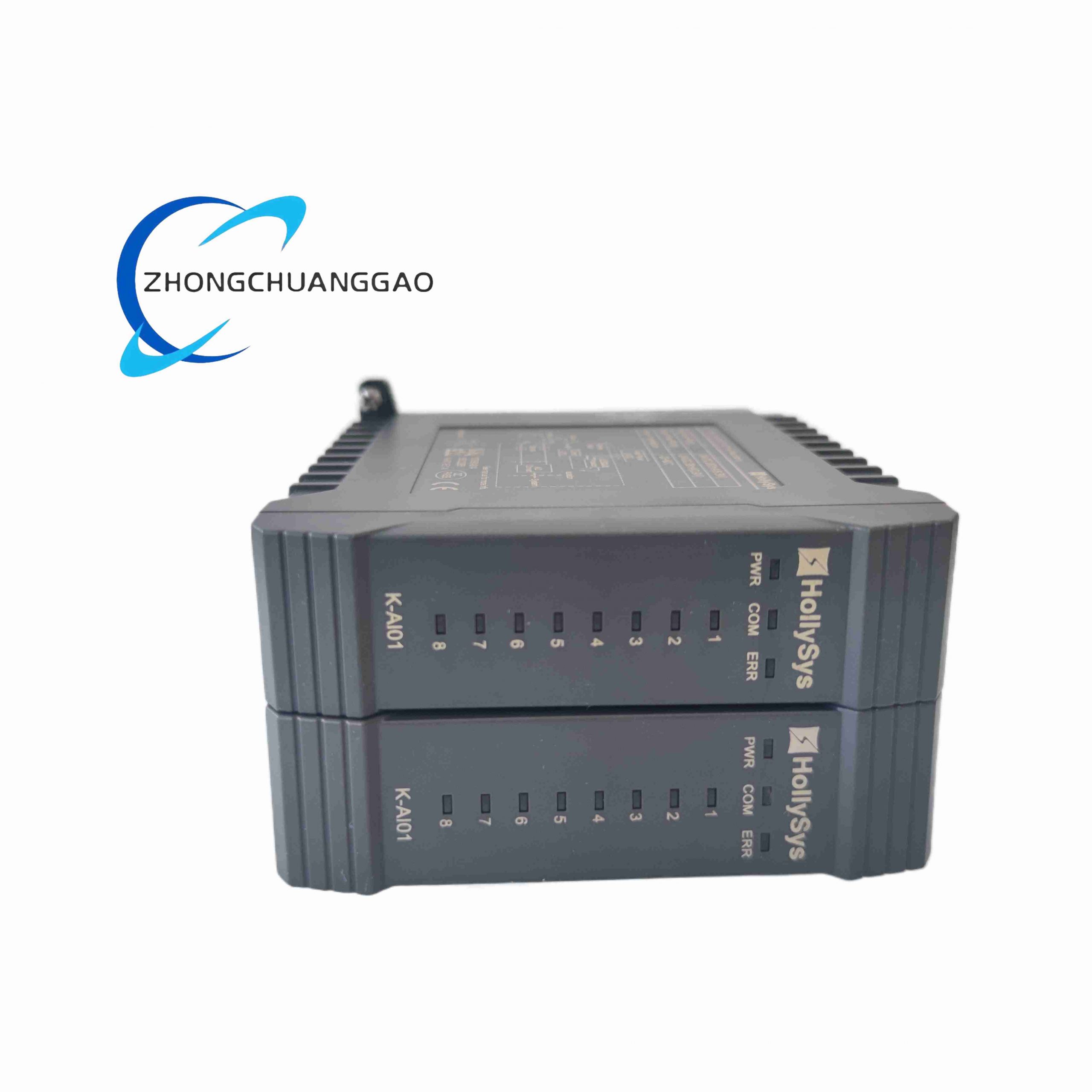
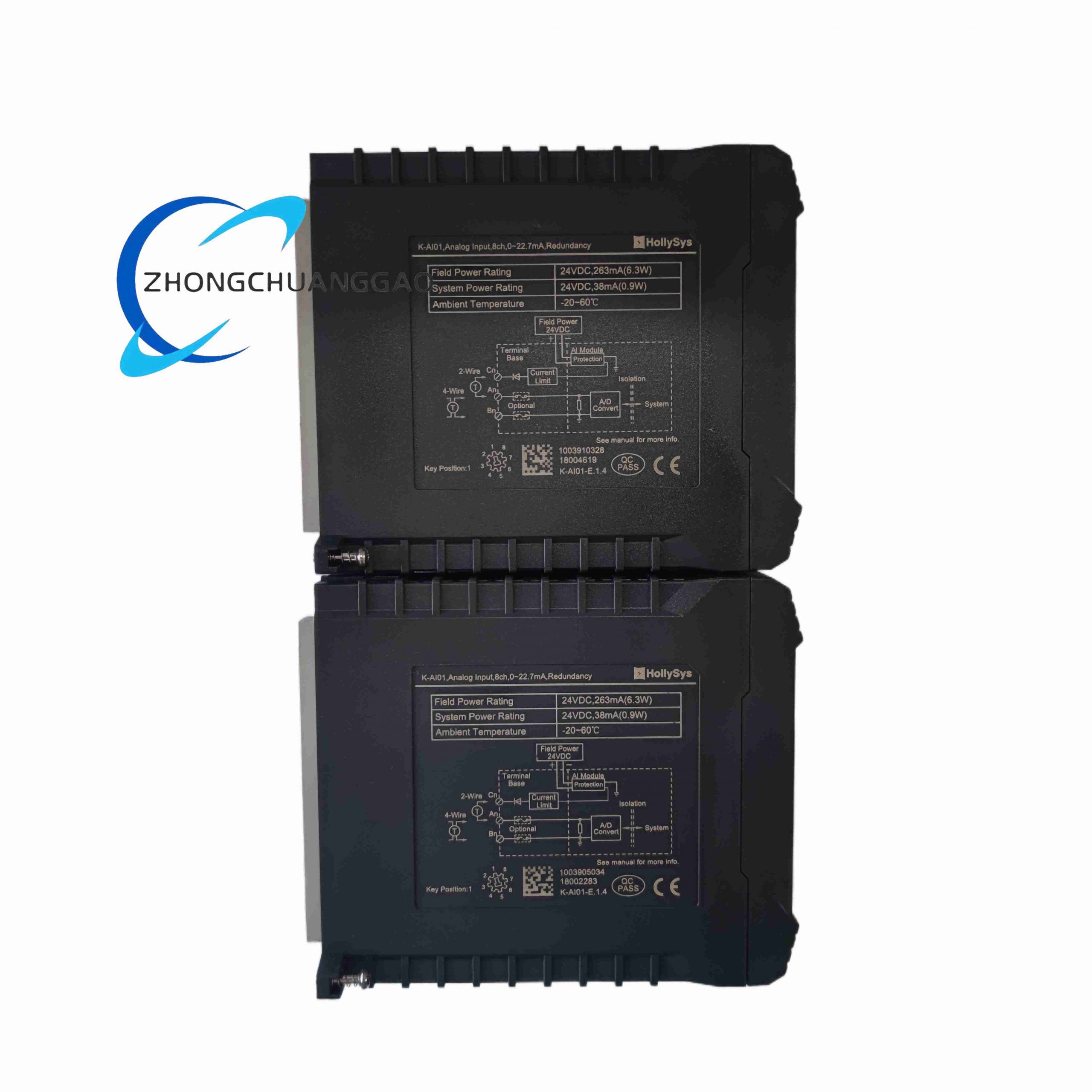
K-AI01 is HollySys (Beijing Hollysys Automation) industrial standard analog input module belonging to the K series modular PLC platform, designed for collecting universal industrial analog sensor signals in process automation plants. It converts 4–20 mA loop current signals from temperature transmitters, pressure sensors, flow meters and liquid level transmitters into standardized digital values for main CPU module processing, with full channel-to-channel galvanic isolation to eliminate ground loop interference in multi-point grounding industrial sites.
Description
Core Technical Specifications & Performance Parameters
- Analog Input Channel Configuration
8 fully isolated analog input channels per module; signal type fixed 4–20 mA DC loop current
- Signal Conversion Precision & Resolution
16-bit A/D analog-to-digital conversion resolution; overall measurement accuracy ±0.1% full scale
- Galvanic Isolation Performance
Channel-to-channel isolation voltage 1500 VAC; field signal side and rack bus logic side isolation 2500 VAC
- Loop Power Supply Support
Onboard built-in 24 VDC loop excitation power for passive two-wire field transmitters
- Backplane Bus Communication Cycle
Analog data scan refresh cycle 2 ms per module; digital data transmission via K series proprietary rack backplane bus
- Environmental Working Parameters
Operating temperature 0 °C ~ +60 °C; storage temperature -30 °C ~ +75 °C; IP20 protection grade inside control cabinet
- Physical Dimension & Weight
Standard DIN rail rack module: 98 mm (height) × 45 mm (width) × 110 mm (depth); net weight 0.28 kg
Material Composition & Structural Features
- Outer housing: Light gray flame-retardant ABS plastic enclosure (UL94-V0 fire rating), integrated DIN rail snap-on buckle at rear
- Internal PCB: Double-sided FR4 circuit board with independent isolated A/D conversion chip per signal channel
- Terminal blocks: Front panel spring-type pluggable terminal blocks for field sensor wiring, anti-loosening spring copper contacts
- Internal components: Isolated signal transformers, 16-bit industrial ADC chips, overvoltage TVS surge protection diodes per channel
- Status indication: Front panel individual channel LED fault indicators, module power and bus communication LED lights
Working Principle
Passive two-wire field sensors connect to module front terminal blocks, powered by onboard built-in 24 VDC loop excitation supply. 4–20 mA analog current signals pass through channel independent isolation transformers to cut off ground loop common-mode interference, then input to dedicated 16-bit A/D conversion chips to convert continuous analog current into discrete digital sampling values. Internal module logic chip packages all 8-channel digital measurement data and transmits to K series CPU master controller via rack backplane bus at fixed 2 ms scan cycle; if any channel open-circuit or over-range signal detected, corresponding channel fault LED illuminates and fault flag data uploaded to CPU for alarm processing.
Application Scenarios
- Thermal power plant boiler water temperature, steam pressure, flue gas flow monitoring
- Chemical petrochemical process tank liquid level, reaction vessel temperature/pressure measurement
- Municipal water supply and wastewater treatment plant flow, PH value transmitter signal collection
- Metallurgy smelting furnace temperature continuous monitoring analog signal acquisition
Installation Requirements
- Mount horizontally on standard 35 mm DIN rail inside IP54 rated electrical control cabinet
- Field sensor signal cables use shielded twisted pair wire, shield single-ended grounded to cabinet PE terminal
- Maintain minimum 10 mm clearance between adjacent I/O modules for heat dissipation
- Two-wire transmitter wiring polarity strictly followed; reverse polarity causes channel open-circuit fault alarm
- Cabinet operating ambient temperature must not exceed 60 °C sustained
Operation & Maintenance Precautions
- Do not apply voltage above 30 VDC to analog input terminals; overvoltage permanently damages isolated ADC circuits
- If channel fault LED activates, first inspect field transmitter wiring continuity before module replacement
- Execute full channel calibration via HollySys AutoThink engineering software after module installation or replacement
- Avoid installation location with corrosive chemical vapor or conductive metal dust accumulation
- Disconnect all field sensor wiring before removing module from DIN rail to prevent live circuit short-circuit
-500x500.jpg)
Reviews
There are no reviews yet.