
Product Short Description
Product Introduction
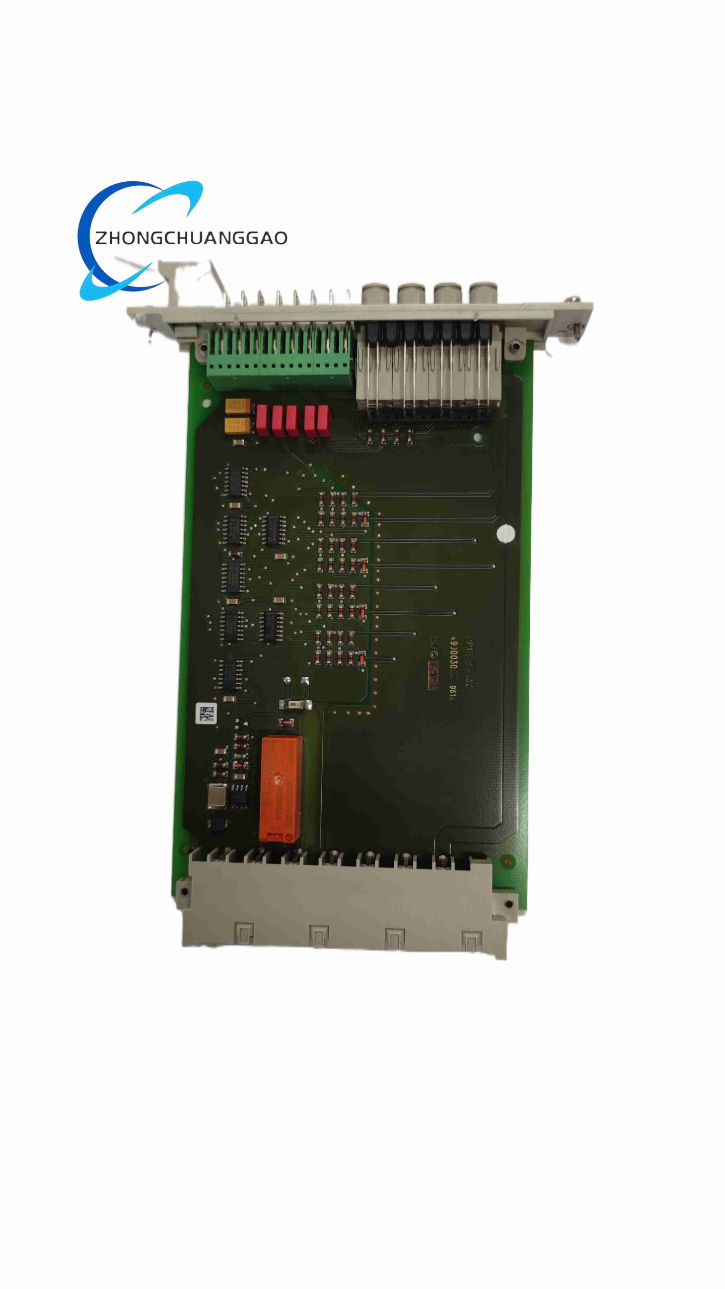
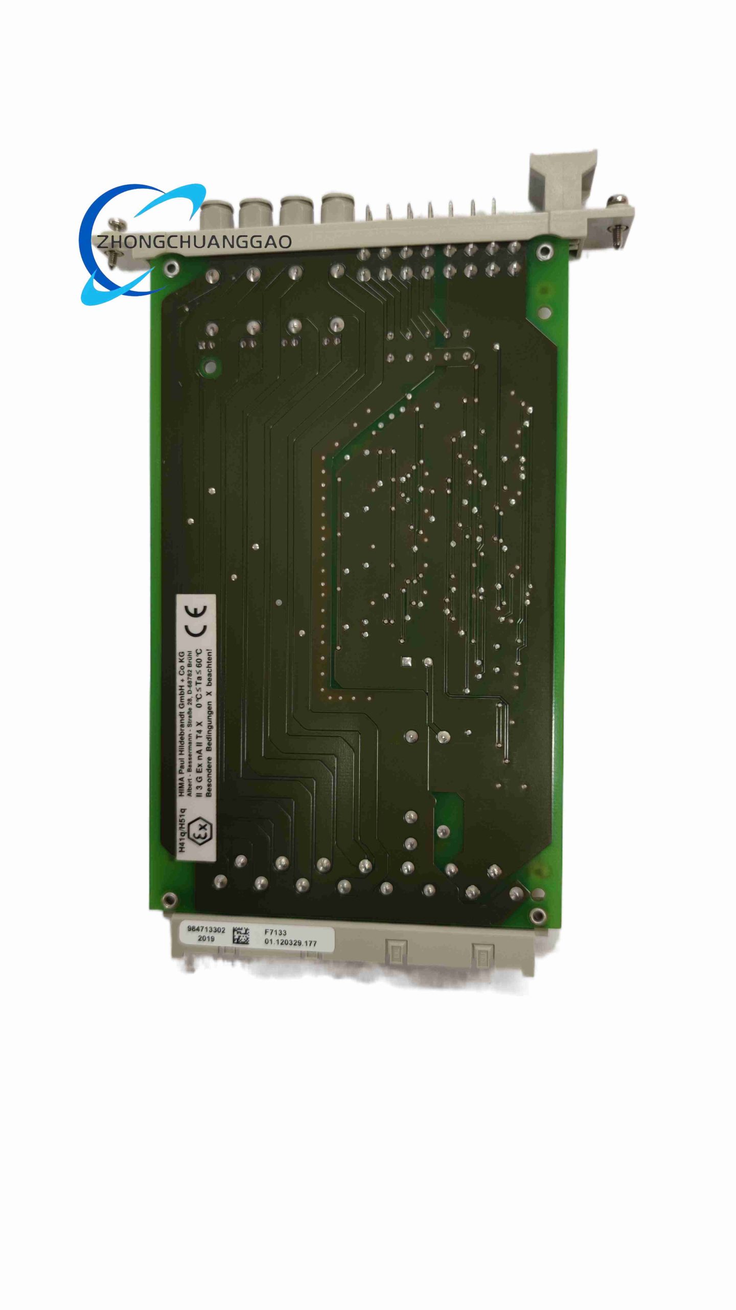
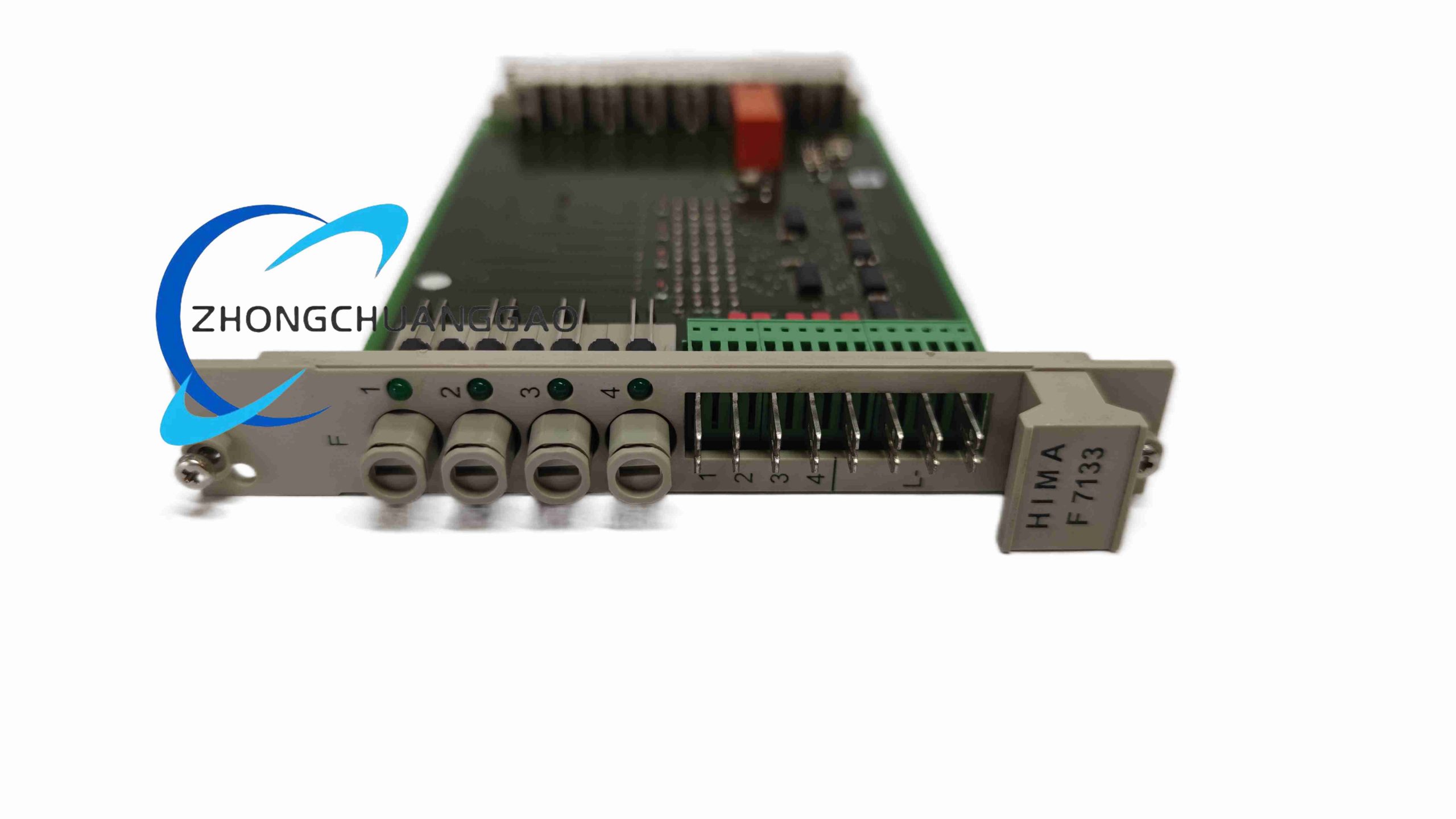
SIL 3 capable auxiliary digital output module dedicated to driving cabinet alarm lights, horn annunciators, local status indication relays and secondary non-critical safety auxiliary loads within Safety Instrumented Systems. Implements full channel circuit self-diagnosis without interfering with primary safety shutdown loops.
Description
Technical Specifications
- Channel Quantity: 8 independent galvanically isolated digital output channels
- Single Channel Rated Continuous Load Current: 100mA resistive load
- Maximum Permissible Inductive Load Power Per Channel: 3W
- Lamp Load Maximum Rating: 2W per channel
- Supply Voltage Range for Field Output: 18VDC ~ 30VDC nominal 24VDC
- Undervoltage Fault Threshold: 16VDC chassis power supply
- Module Power Consumption: 5VDC bus = 95mA; additional 120mA under full 8-channel loaded condition
- Rack Unit Width: 4 TE standard DIN rack slot
- Safety Certification: IEC 61508 SIL 3 auxiliary component, TÜV Rheinland AK6, CE, UL Listed
- Operating Ambient Temperature: -20°C ~ +70°C
- Storage Temperature Range: -40°C ~ +85°C
- Relative Humidity: 5% ~ 95% non-condensing
- Ingress Protection Grade: IP20, indoor control cabinet mounting only
Function Features
- Per-channel cyclic wire break, short-circuit and supply undervoltage automatic fault diagnosis
- Fail-safe de-energized output logic; all channels cut off upon internal module critical hardware failure
- Low-amplitude non-intrusive test pulse injection for loop integrity verification, no visual flicker on indicator lamps
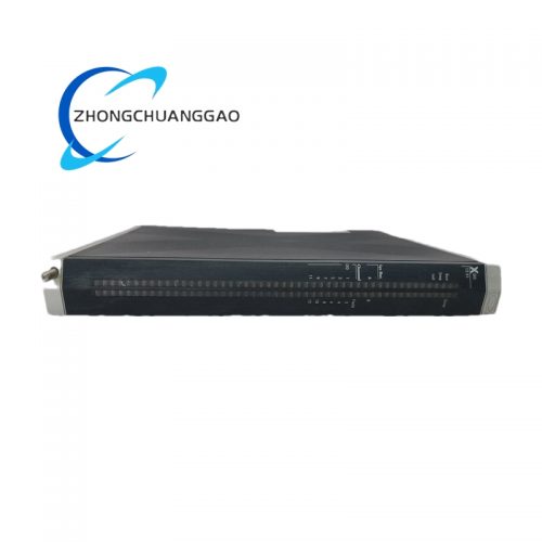
- Individual front-panel LED status indicator for each of the 8 output channels
- Complete galvanic isolation between backplane safety communication bus and field auxiliary output circuits
- Hot-swappable operation supported in fully redundant HIMA safety rack architectures
- Separate detachable wiring terminal plug for field cable maintenance without full chassis power shutdown
Performance Parameters
- Channel fault diagnostic response latency: <12ms
- Maximum allowable field wiring loop resistance per single channel: 30Ω
- Diagnostic test pulse duration: 150μs, no visible interference to alarm indicators
- Transient overvoltage withstand capacity per output channel: 36VDC surge
- Diagnostic hardware coverage rate: 99.8% for all on-board drive circuits
Material Composition
- Outer Housing: UL94 V0 flame-retardant reinforced injection molded ABS plastic
- Main Printed Circuit Board: Double-sided high-temperature FR4 industrial grade substrate
- Drive Semiconductors: Wide-temperature industrial MOSFET power switching chips
- Wiring Terminals: Nickel-plated copper alloy terminals with anti-oxidation coating
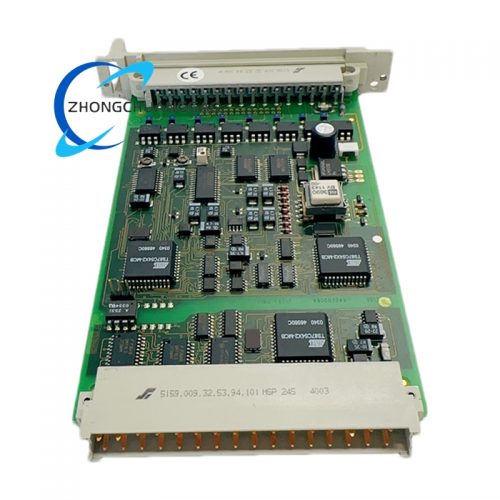
- Backplane Connector: Multi-point gold-plated edge contact bus connector
- Internal Diagnostic Controller: Low-power industrial wide-temperature microcontroller
Structural Characteristics
- Standard pluggable DIN rail rack module with front mechanical locking clip
- Front panel linear array of 8 independent LED status indicators matching each output channel
- Physically separated terminal plug compartment isolated from internal control circuits
- Internal segmented isolation barriers separating low-voltage backplane bus and field output power circuits
- Compact 4TE width to minimize occupied rack slot space for multi-module cabinet layouts
Working Principle
Safety auxiliary trigger commands transmitted from HIMA main CPU via redundant backplane safety bus to the module’s internal microcontroller. Each isolated MOSFET drive channel supplies regulated 24VDC power to field alarm and indication loads. Periodic low-energy diagnostic pulses are injected into each output wiring loop to measure circuit impedance values; abnormal impedance readings trigger fault flag transmission to the main safety CPU. In the event of module internal hardware failure, all output channels are forced to de-energized safe state to avoid false alarm actuation.
Advantage Highlights
- Optimized low-current channel rating specifically designed for alarm horn, beacon light and small indication relay loads
- Non-intrusive diagnostic test pulses eliminate visual flickering of cabinet status lamps during cyclic self-testing
- Compact form factor reduces overall cabinet size and hardware procurement costs for auxiliary signal distribution
- Full channel galvanic isolation blocks ground loop noise and cross-channel signal interference
- Wide operating temperature range supports installation in unconditioned field control cabinets
- Hot-swap maintenance capability reduces planned system downtime during module replacement
Applicable Industries
Onshore & Offshore Oil and Gas Process Safety Cabinets, Refinery SIS Alarm Annunciation Systems, Thermal Power Plant Boiler Safety Indication Panels, LNG Storage Terminal Overfill Warning Light Control, Hazardous Chemical Reactor Local Alarm Circuits, Pharmaceutical Batch Process Safety Status HMI Auxiliary Signals
Installation Requirements
- Install exclusively within certified HIMA Planar F series DIN rail safety chassis
- All field auxiliary wiring must use shielded twisted-pair cables with single-end grounding at cabinet master ground bar
- Strictly restrict single-channel load current below 100mA continuous rated value
- Maintain a minimum 20mm vertical ventilation gap between adjacent rack modules for heat dissipation
- Separate low-current auxiliary output wiring from high-power motor and valve control cables with minimum 25cm routing distance
- Anti-static wristband is mandatory for all module handling, installation and replacement operations
Usage Precautions
- Do not connect loads exceeding 3W inductive or 2W lamp power rating on any single channel
- Conduct full channel short-circuit and open-wire simulation testing during annual SIS proof test cycles
- Replacement wiring terminal plugs must be original factory HIMA spare parts; third-party terminals invalidate SIL certification
- Prohibit installation in environments with continuous corrosive gas, heavy oil mist or direct liquid splashing
- Verify chassis 24VDC power supply maintains voltage above the 16VDC undervoltage trip threshold at all operating times
- Avoid stacking heat-generating high-power I/O modules directly adjacent to F7133 to prevent over-temperature operation
提供HIMA F7133的详细参数
HIMA F7133的应用案例
HIMA F7133的市场价格
Reviews
There are no reviews yet.