
Description
Product Overview
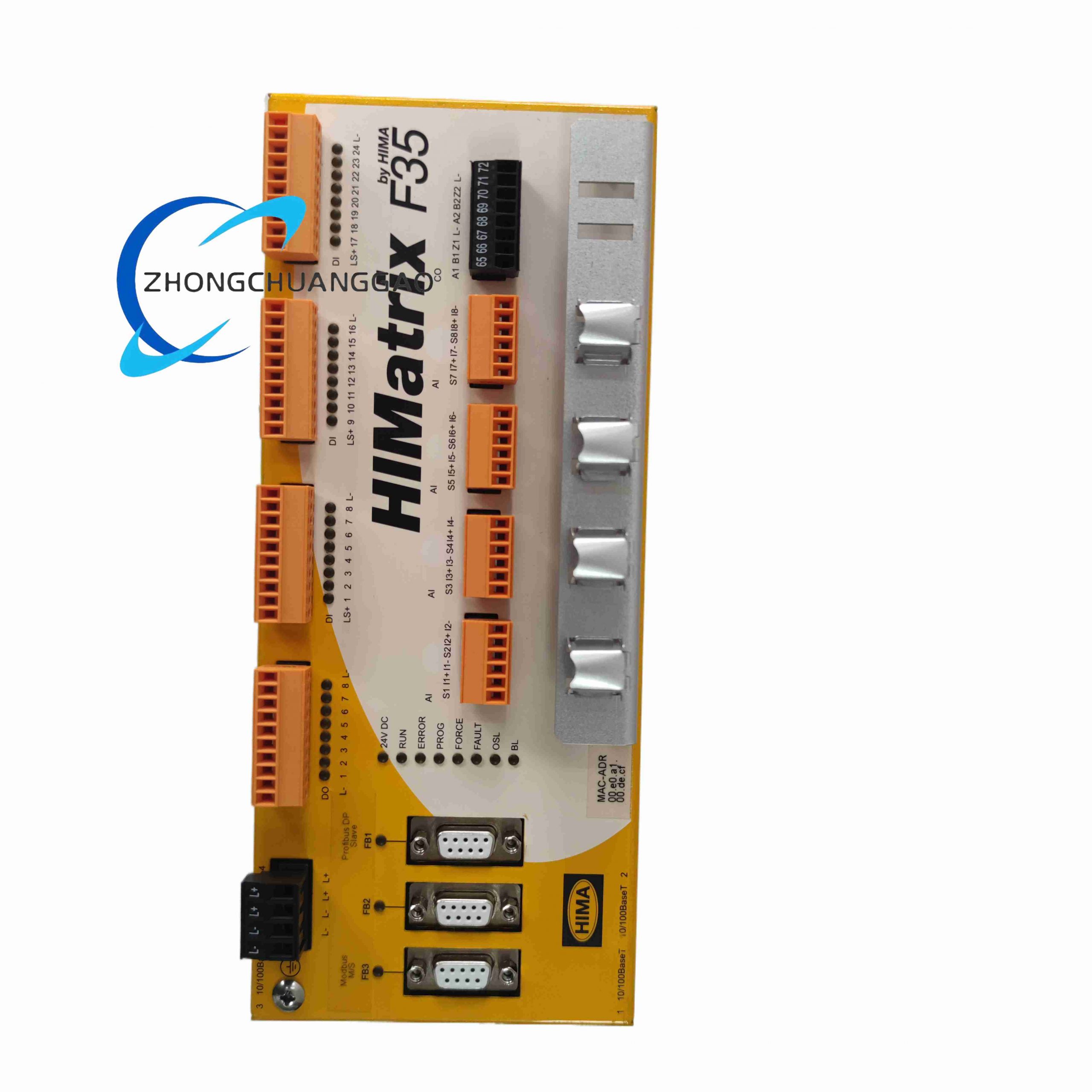
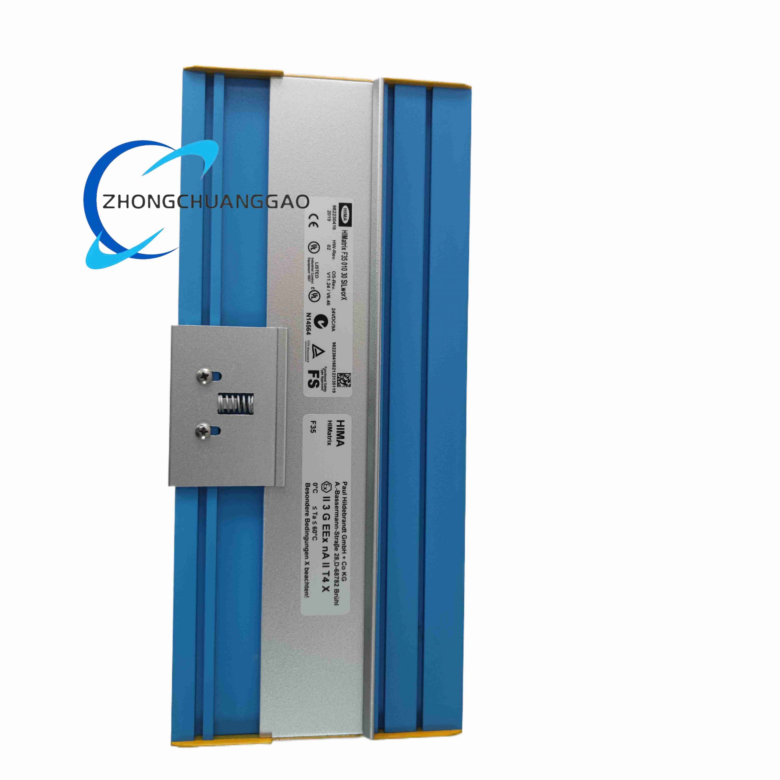
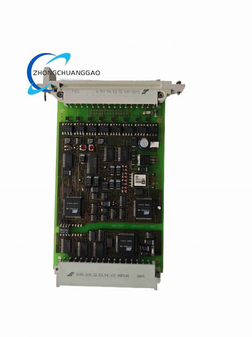
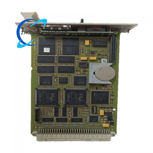
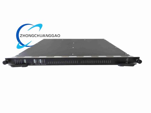
HIMA F3501030 (part code 982200416) is a fully integrated standalone compact safety controller within the HIMatrix distributed safety system product line, combining native digital input channels, relay digital output channels, pulse counter inputs, and multi-protocol communication interfaces into single DIN rail mount hardware without separate expansion I/O racks required. It executes complete SIL3 safety logic for small-to-medium safety loops including machine safety interlocks, boiler burner management, local ESD sub-systems, and process auxiliary safety protection circuits, fully certified to global functional safety standards.
Technical Specifications
- Overall Physical Dimension: 257 mm × 114 mm × 97 mm
- Net Weight: 1.2 kg
- Primary Operating Power Supply: 24 V DC, tolerance range -15% to +20% supply voltage fluctuation
- Digital Input Channels: 16 sink/source configurable 24 V DC safety digital input points
- Digital Relay Output Channels: 8 dry contact mechanical relay safety output points
- Pulse Counter Inputs: 2 × 100 kHz high-speed safety pulse counting channels
- Analog Auxiliary Input Support: Expandable 8 analog input points via compatible HIMatrix expansion modules
- Per Channel Input Rated Current: 10 mA per digital input channel
- Per Channel Output Contact Current Rating: 0.5 A resistive load per relay output channel
- Full Load Maximum Power Consumption: 12 W; no-load static power draw 6 W
- Signal Response Latency (I/O Channel): ≤ 20 ms input/output full cycle response
- Operating Temperature Range: 0 °C to +60 °C
- Storage Temperature Range: -40 °C to +85 °C
- Safety Certification: IEC 61508 SIL 3, IEC 61511, ISO 13849-1 PL d, ATEX Zone 2 certified
- EMC Compliance Standard: EN 61000-6-2 industrial heavy electromagnetic interference rating
Function Features
- All-in-one integrated safety controller combining DI, DO, high-speed pulse counter, and communication interfaces single hardware unit
- 16 configurable sink/source 24 V DC digital safety input channels for field safety sensor connection
- 8 mechanical dry contact relay safety outputs for solenoid valve, safety trip actuator, and alarm horn control
- Dual 100 kHz pulse counter channels for safety speed monitoring, flow pulse, and rotary encoder safety signal processing
- Dual redundant communication interfaces: CANopen safety bus, RS485 serial, and Ethernet SafeEthernet protocol support
- Real-time full channel I/O diagnostic for open circuit, short circuit, and power supply fault detection
- Fail-safe relay output de-energized default state upon controller hardware or power supply fault event
Performance Parameters
- PFHD (Probability of Failure on Demand Dangerous): < 1 × 10⁻⁹ / hour SIL3 compliant
- Diagnostic coverage rate for all internal and I/O channel faults: 99.7%
- MTTFd under full rated operating load conditions: > 2,480,000 hours
- Safety logic execution cycle time: configurable 5 ms minimum scan interval
- Continuous 24/7 operation duty cycle: 100% rated non-stop service
- Pulse counter maximum input frequency: 100 kHz continuous stable signal processing
Material Composition
- Main Controller Housing: UL94-V0 flame retardant reinforced PA66 industrial plastic DIN rail enclosure
- Main Circuit PCB: Double-sided FR4 moisture-resistant flame retardant printed circuit board
- Relay Output Contact Components: Silver alloy anti-wear mechanical safety relay contactors
- Input Channel Isolation Hardware: High-voltage optocoupler galvanic isolation arrays per DI channel
- Communication Port Connectors: Nickel-plated copper alloy screw terminal block connectors
- Internal Processor IC: Dual redundant wide-temperature industrial safety microcontroller chipset
Structural Characteristics
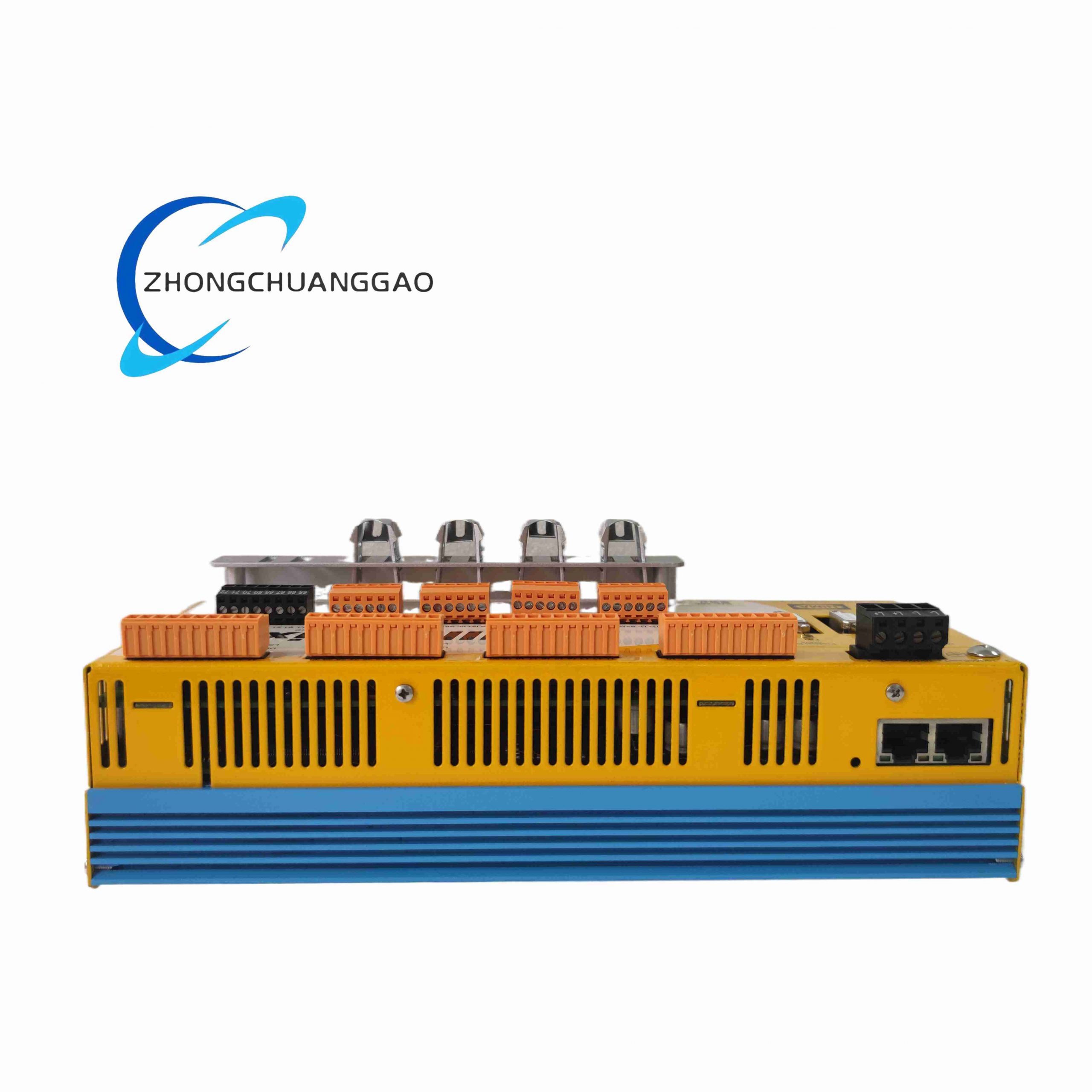
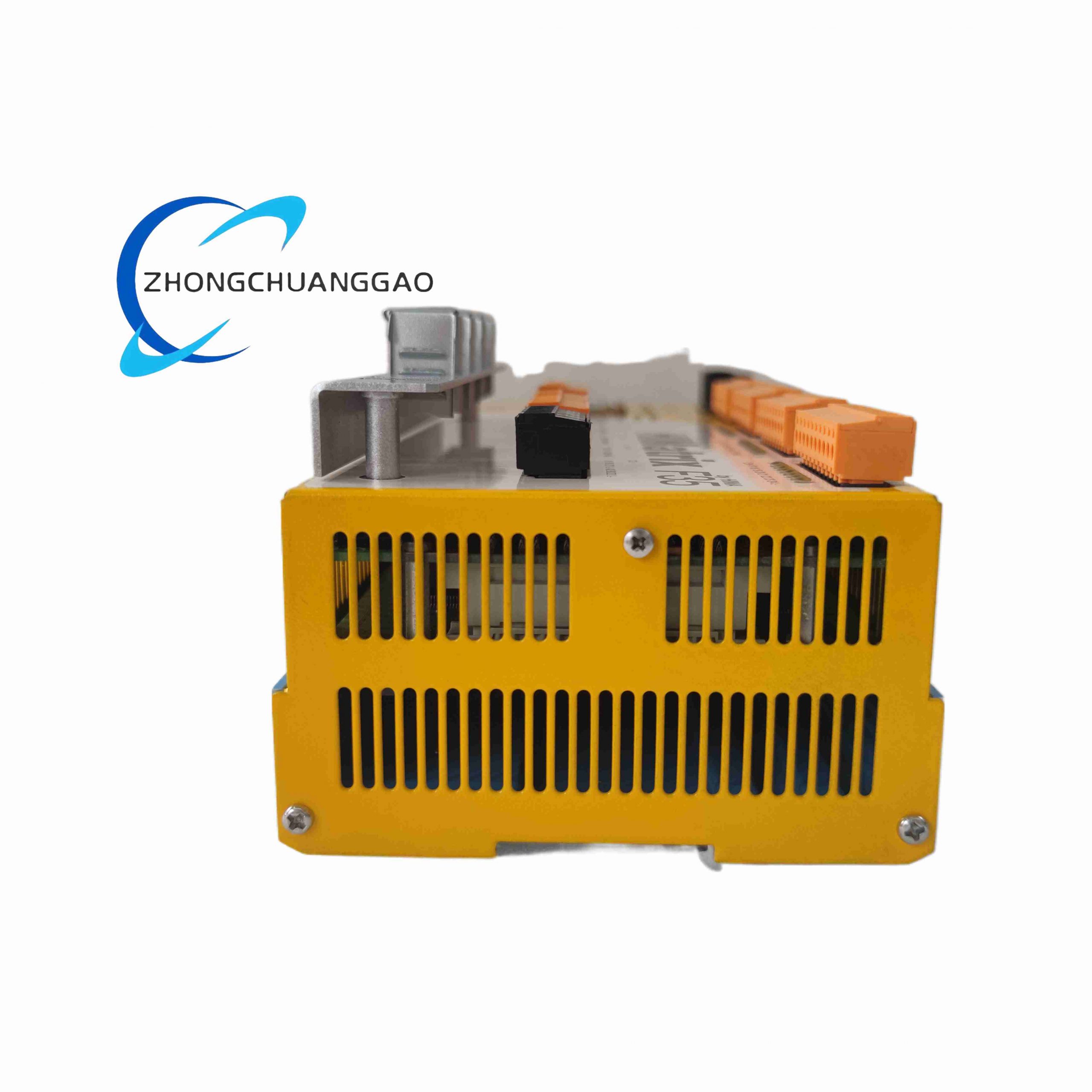
- Standard 35 mm DIN rail vertical compact single-block integrated controller form factor, no rack backplane required
- Front panel segmented screw terminal blocks segregated into power, digital input, relay output, counter, and communication terminals
- Multi-color front panel LED indicators for power supply, run status, channel fault, communication link alarm
- Internal dual redundant power supply circuit with automatic single power failure fault tolerance
- IP20 front enclosure dust ingress protection rating for industrial control cabinet installation
- Internal heat sink aluminum alloy plate for passive natural convection thermal dissipation
Working Principle
Dual redundant safety microcontroller cores execute user-programmed SIL3 safety logic downloaded via HIMA ELOP II factory programming software. Field safety sensor 24 V DC digital input signals pass through per-channel galvanic isolation optocouplers before digital sampling by the safety processor; high-speed pulse counter channels process rotary encoder and flow meter pulse signals for safety speed and flow limit interlock logic. Upon safety logic trip condition detection, internal mechanical safety relay outputs de-energize to safe default state to cut actuator power supply. Integrated continuous self-test circuits sample all internal power, processor, and I/O channel hardware every logic scan cycle; detected faults trigger front panel fault LED alarm and transmit diagnostic data via CANopen or Ethernet communication ports to remote monitoring systems. Dual redundant processor cross-check all safety computation results to eliminate single-core dangerous failure risk.
Advantage Highlights
- Standalone all-in-one compact design eliminates requirement for separate CPU and I/O expansion racks for small safety systems
- Dual redundant processor architecture achieves full SIL3 functional safety certification per IEC 61508
- Integrated high-speed 100 kHz pulse counter channels support safety rotary machinery overspeed protection logic
- Multi-protocol communication compatibility enables seamless integration with plant DCS and distributed HIMatrix safety controllers
- Fail-safe de-energized relay output design complies with global process safety ESD and interlock standards
- ATEX Zone 2 hazardous area certification permits installation inside sheltered classified industrial control cabinets
Applicable Industries
Small batch chemical manufacturing auxiliary safety interlocks, industrial boiler burner management systems, food processing machinery safety protection, mining local conveyor safety trip panels, thermal power plant auxiliary pump safety control, pharmaceutical process safety sub-systems
Installation Requirements
- Mount directly to standard 35 mm DIN rail inside IP20 rated industrial control cabinet enclosures
- Maintain minimum 20 mm vertical ventilation gap above and below controller housing for passive heat dissipation
- External 24 V DC power supply protected with 10 A time-lag T-type slow blow safety fuse
- All field sensor and actuator wiring uses shielded twisted pair cable with cabinet single-end grounding only; multi-point grounding is forbidden.
- Cabinet ambient environment requires relative humidity 5%–90% non-condensing, zero exposure to corrosive gas, oil mist or conductive dust.
- All wiring terminals must be torqued to 0.8 N·m standard torque value to prevent loose contact and signal fault.
- ATEX Zone 2 installation requires the whole control cabinet to reach certified Ex nA enclosure grade with internal purging device if placed in classified hazardous zones.
Usage Precautions
- Hot swapping of the whole controller unit is strictly prohibited; cut off 24 V DC main power before dismounting or mounting.
- Do not connect AC voltage signals to digital input channels; all field input signals are limited to rated 24 V DC only.
- Mechanical relay outputs cannot drive loads exceeding 0.5 A resistive load; external intermediate relay must be added for high-current actuators.
- Safety logic programming, parameter modification and fault reset operations can only be completed by HIMA ELOP II dedicated software.
- Quarterly inspection of front LED indicators and terminal block tightness is mandatory for long-term stable operation.
- Condensation inside enclosure will cause irreversible short-circuit damage to internal PCB; install cabinet heater if ambient temperature fluctuates sharply.
- Spare controllers must be stored in anti-static ESD packaging under constant 18–22 °C temperature environment.
Reviews
There are no reviews yet.