
Product Short Description
Product Name: Foxboro I/A Series FBM06 Mixed-Signal Module, 4 Pulse Inputs and 4 Analog Outputs
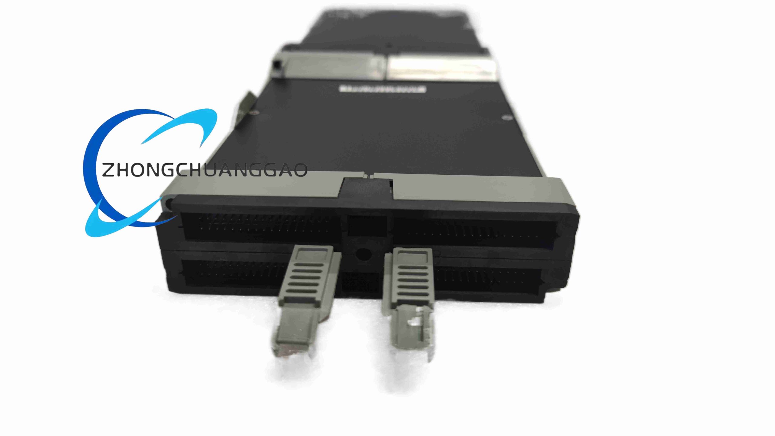
Product Overview: FBM06 is a Field Bus Module for the Foxboro I/A Series distributed control system. It combines pulse or frequency acquisition with analog current output on one electronic module to reduce cabinet slot count for flow, speed and small control-loop applications.
Description
Technical Specifications: 4 independent pulse inputs; 4 independent analog outputs; pulse input range typically 0 to 20 kHz DC-coupled, with selected versions rated to 50 kHz; analog output standard 0 to 20 mA, software-configurable for 4 to 20 mA; common part reference P0400YG; 100 Series carrier compatible; upgrade path to 200 Series FBM206 or P0916-class terminal assemblies according to system revision.
Functional Features: Each pulse channel converts turbine, vortex, encoder or contact pulses into frequency, counts or engineering values. Each analog output channel drives control elements with isolated current signaling. Module reporting includes channel status through system diagnostics and terminal-assembly LEDs where fitted.
Application Scenarios: Vortex or turbine flow metering, rotational speed monitoring, totalization, local set-point output, actuator driving for valves or variable-speed equipment, and mixed pulse-plus-analog skids in chemical, oil and gas, power and water treatment plants.
Performance Parameters: Typical frequency accuracy within ±0.1 percent of calibrated range; analog output resolution and accuracy governed by 12 to 16-bit DAC architecture depending on firmware and carrier; output load capability aligned to standard 4 to 20 mA loops with 250 to 750 ohm total circuit resistance; electrical isolation between inputs, outputs and backplane.
Material Composition: Industrial multilayer PCB, surface-mount signal components, metal backplane connector, molded insulating housing, and corrosion-resistant hardware for control-room or G3-classified field enclosures.
Structural Characteristics: Electronic module plugs into the I/A input/output baseplate; pulse and analog fields require the correct terminal assembly; internal galvanic isolation barriers separate field wiring from system logic; labeling and LED indicators support field identification.
Working Principle: Pulse inputs are conditioned, filtered and counted by the module timing circuitry; converted values are transmitted over the I/A fieldbus to the control processor. Analog output channels receive digital demand values from the controller, convert them through per-channel DAC and current drivers, and transmit isolated 0 to 20 mA or 4 to 20 mA signals to field instruments.
Installation Requirements: Install only in the designated I/A baseplate and carrier; fit the correct terminal assembly for pulse and analog wiring; use shielded twisted pairs for frequency inputs; ground shields at the defined single point; verify 24 V backplane or carrier power before insertion; confirm 100 Series versus 200 Series compatibility before replacement.
Usage Precautions: Do not connect voltage levels above the approved pulse input rating; confirm wet, dry or open-collector sensor type before termination; avoid mixing FBM06 100 Series firmware with FBM206 200 Series baseplates unless the migration rule is verified; check output loop resistance before energizing analog outputs; perform functional testing with the control system in maintenance mode.

Reviews
There are no reviews yet.