
Product Short Description
Product Overview
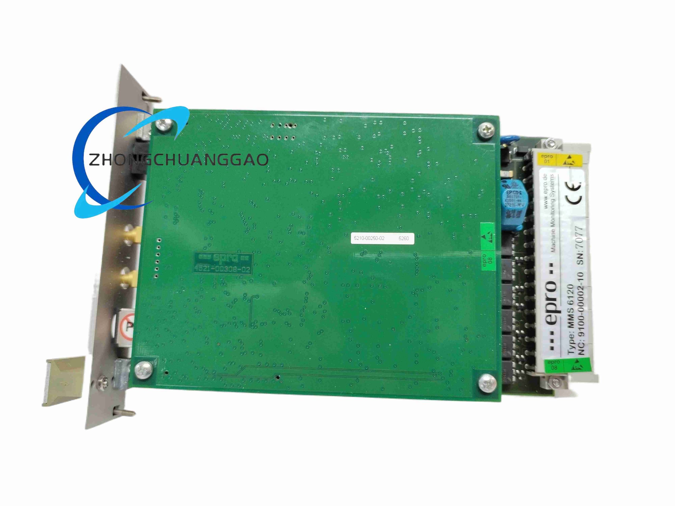
MMS6120 is rack-mounted dual-channel vibration monitoring module manufactured by EPRO (Baker Hughes condition monitoring division), dedicated to measuring absolute bearing housing vibration via electrodynamic velocity sensors or piezoelectric acceleration transducers on rotating machinery. Each channel operates fully independently to monitor two bearing positions simultaneously, convert raw vibration waveform into standard industrial analog signals, and execute multi-stage alarm threshold judgment for turbine, compressor and fan safety protection
Description
Core Technical & Performance Parameters
- Channel quantity: 2 fully independent isolated measurement channels
- Supported sensor types: PR9266/PR9268 electrodynamic velocity sensors, piezoelectric acceleration sensors
- Frequency measurement range: 10 Hz ~ 1000 Hz (standard variant); optional extended 5 Hz ~ 1600 Hz bandwidth
- Vibration measurement metrics: Velocity RMS (mm/s), displacement peak-to-peak, acceleration peak value
- Adjustable measurement range: 0 ~ 100 mm/s continuously configurable via configuration software
- Measurement accuracy: ±1% full scale; Linear error <0.5% across full bandwidth
- Signal output per channel: Isolated 4–20 mA current output, isolated 0–10 V DC voltage output, buffered raw vibration waveform BNC output
- Communication interface: Front panel RS232 local configuration port, rear rack RS485 Modbus RTU remote data transmission
- Power supply: Redundant 18–31.2 VDC dual power input, reverse polarity protection
- Power consumption: Max 2 W low power operation
- Operating temperature: 0°C ~ +65°C; Storage temperature: -20°C ~ +75°C
- Alarm configuration: Two programmable alarm levels (Warning / Danger) with adjustable hysteresis to eliminate false triggering during equipment speed ramp-up
- Galvanic isolation: 2500 VAC isolation between sensor input, analog output, power supply circuits
Function Features
- Dual fully isolated measurement channels eliminate cross-talk interference between two bearing monitoring points, suitable for separate left/right bearing synchronous monitoring of rotating shafts.
- Built-in digital band-pass filtering, programmable low/high cut frequency to filter irrelevant mechanical background noise and retain only equipment fault characteristic vibration frequency bands.
- Multi-parameter real-time calculation: Simultaneously output vibration velocity, displacement and acceleration values without external signal conditioning modules.
- Sensor circuit continuous diagnostic function: Automatically detect open-circuit, short-circuit and sensor coil degradation faults, trigger dedicated sensor failure alarm contact output.
- Password-locked configuration parameter storage in non-volatile EEPROM; parameters retained after complete power loss without backup battery.
- Buffered raw vibration waveform output via front BNC connectors for portable spectrum analyzer offline fault frequency analysis.
- Modbus RTU communication transmits real-time vibration amplitude, alarm status and sensor health data to DCS, SCADA or local HMI systems for remote equipment condition monitoring.
- Independent potential-free relay alarm contacts for Warning and Danger levels to trigger external audible/visual alarm or machine emergency shutdown logic.
Material Composition & Structural Characteristics
- Rack chassis: Standard 19-inch 3U subrack pluggable module housing, cold-rolled steel front panel with black matte anti-scratch coating.
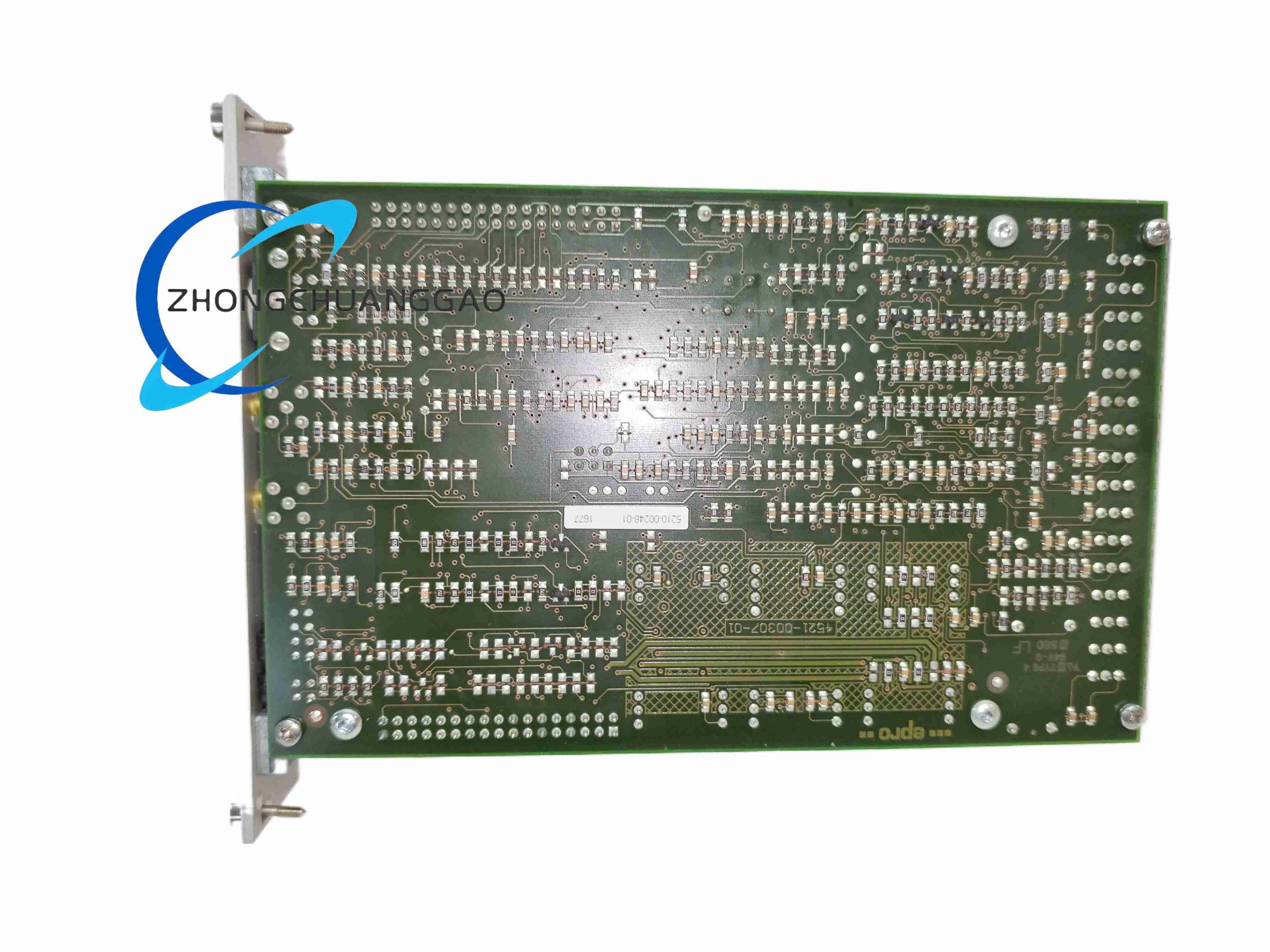
- Measurement PCB: Multi-layer FR4 PCB with full polyurethane conformal coating to resist oil mist, dust and condensation in turbine house environments.
- Signal isolation components: High-performance optocoupler galvanic isolation chips separating low-level sensor input from high-voltage relay output circuits.
- Terminal connectors: Rear screw terminal strip for sensor wiring, power supply and relay alarm wiring, nickel-plated anti-oxidation contact pins.
- Front panel interfaces: BNC coaxial connectors for raw vibration signal output, 9-pin RS232 D-SUB configuration port, LED indicators for Power, Channel Fault, Warning Alarm, Danger Alarm.
Working Principle
Low-amplitude analog vibration signal from electrodynamic velocity sensor enters high-impedance differential input circuit, passes through programmable digital band-pass filter to remove interference frequency components. Onboard 24-bit ADC converts filtered analog waveform into digital signal, microcontroller calculates vibration RMS velocity, peak displacement and acceleration values in real time. Calculated measurement values are compared against user-programmed Warning and Danger threshold setpoints; relay contacts activate if measured value exceeds threshold. Processed measurement data is converted to isolated 4–20 mA / 0–10 V standard analog output and transmitted via RS485 Modbus bus to upper monitoring system. Continuous sensor circuit impedance measurement detects sensor wiring faults and outputs dedicated fault alarm signal.
Installation Requirements
- Install module into EPRO standard MMS6000 series 19-inch rack subrack, fully seat module backplane connector and lock front panel screw to avoid vibration-induced loose contact.
- Sensor signal wiring must use shielded twisted pair low-noise cable; cable shield grounded single-point at module rear terminal only, double-point grounding creates ground loop vibration measurement noise.
- Maintain minimum 50cm routing separation between sensor signal cables and high-voltage motor power cables to prevent electromagnetic interference distorting vibration waveform readings.
- Dual redundant DC power input wiring recommended for critical turbine/compressor protection systems; connect two independent 24 VDC power supplies to eliminate single power failure risk.
- Alarm relay output wiring must use separate cable trunking isolated from low-level sensor signal wiring.
- Rack installation environment must avoid direct oil mist splash; install air filter ventilation on rack cabinet to reduce PCB contamination.
Application Scenarios
Steam/gas turbine bearing protection, centrifugal compressor condition monitoring, large industrial fan/blower vibration safety system, gearbox health monitoring, generator set bearing vibration protection, centrifugal pump predictive maintenance monitoring.
Operation & Maintenance Precautions
- Calibrate module vibration measurement range every 12 months with standard vibration signal calibrator; long-term operation drifts ADC conversion accuracy leading to false alarm triggering.
- Do not disconnect sensor cables while module is powered live; open-circuit sensor input triggers permanent Warning alarm state requiring manual parameter reset.
- Front BNC raw signal output terminals cannot be short-circuited to ground; short circuit damages internal buffer operational amplifier chip.
- Cabinet ambient temperature exceeding 65°C for continuous operation accelerates EEPROM parameter storage failure and microcontroller calculation drift.
- Modbus RS485 bus must install terminal resistance jumper at two bus endpoints; missing termination resistor causes unstable remote data reading and packet loss.
- Avoid mechanical shock impact on module front panel during rack maintenance; internal precision analog components are sensitive to physical vibration and impact damage.
Reviews
There are no reviews yet.