
Product Short Description
Product Overview
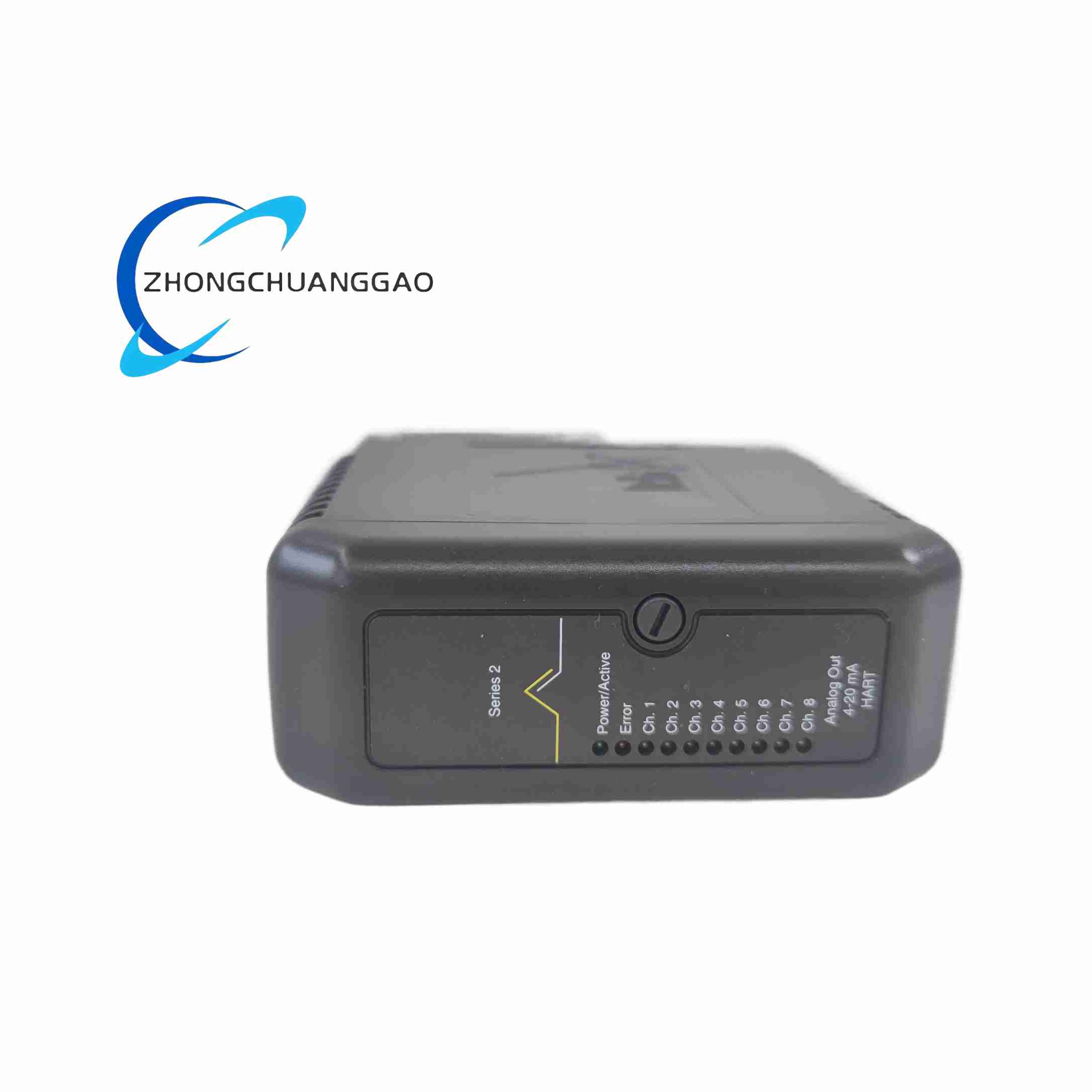
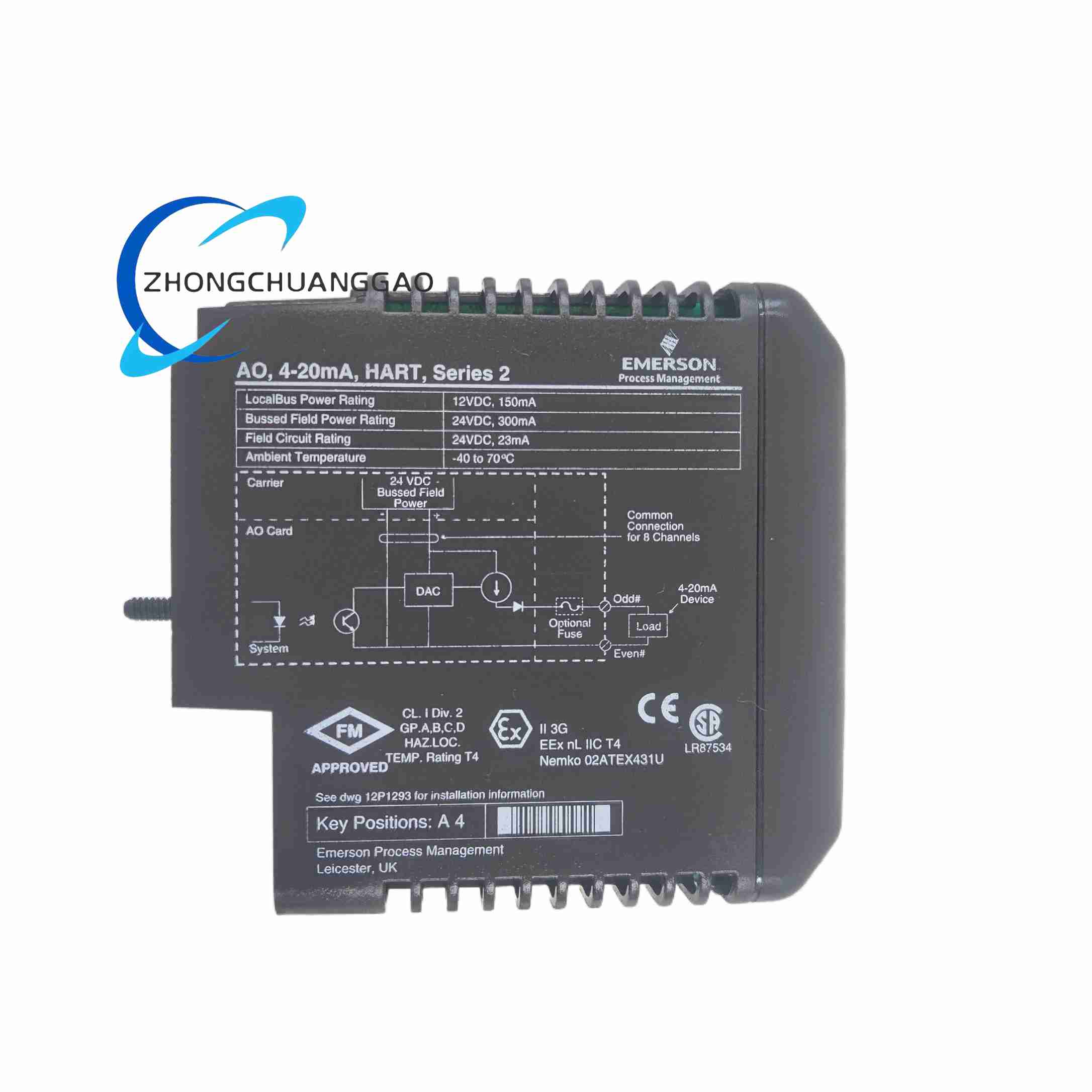
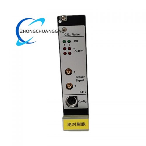
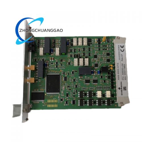
SS4310T01 is a field-mounted isolated analog signal acquisition terminal module developed exclusively for Emerson DeltaV distributed control systems. It serves as the intermediate signal conditioning unit between field process transmitters and DeltaV system I/O cards. This specific T01 variant features single-channel galvanic isolation, optimized for 4–20mA two-wire loop-powered transmitters widely used in petrochemical, power and water treatment industries.
Description
Core Technical Specifications
- Operating Supply Voltage: 24 VDC system control power, 12mA typical consumption
- Supported Field Signal Type: 4–20mA two-wire loop transmitter
- Isolation Rating: 2500 VAC galvanic isolation between field side and DCS system side
- Signal Input Channel: Single independent analog input channel
- Loop Supply Output to Field Transmitter: 26 VDC nominal open-circuit voltage, maximum 22mA drive current
- Input Signal Filtering: Built-in 4th-order low-pass analog filter, configurable cutoff frequency 10Hz / 100Hz
- Common-Mode Noise Rejection Ratio: 110dB at 50/60Hz industrial power frequency
- Surge Withstand Capability: IEC 61000-4-5, 2kV surge protection on field wiring terminals
- Operating Ambient Temperature: -40°C ~ +70°C
- Storage Temperature: -45°C ~ +85°C
- Relative Humidity Tolerance: 5%–95% non-condensing
- Mounting Standard: 35mm standard DIN rail vertical installation
- Overall Dimensions: 110mm height × 22.5mm width × 85mm depth
- Net Weight: 0.18kg
- Certifications: CE, UL, ATEX non-hazardous area certification, IEC 61010
Material Composition & Structural Features
- DIN Rail Housing: Flame-retardant PA66 gray plastic injection molded enclosure, rear integrated elastic DIN rail buckle for tool-free installation and removal
- Internal Circuit Substrate: Double-sided FR-4 flame retardant printed circuit board, partial conformal acrylic coating on signal isolation and surge protection circuits
- Core Electronic Components: High-precision low-drift signal isolation optocouplers, low-temperature drift sampling resistors, multi-stage LC EMI filter inductors, gas discharge tube surge suppressors, low-noise operational amplifiers
- Wiring Terminal Structure: Front-facing spring push-in terminal blocks, two separate terminal groups clearly divided as field wiring terminals and DCS backplane wiring terminals; terminal surfaces engraved with clear polarity and signal identification marks
- Status Indication System: Two high-brightness LED indicators on front panel; green LED for power supply normal status, amber LED for field loop open-circuit fault alarm
- Internal Isolation Partition: Integrated plastic insulation barrier between field signal circuit and system-side circuit to enhance isolation safety performance and prevent cross-circuit leakage current interference
Working Principle
- 24VDC control power input energizes the module internal power isolation circuit, generating independent isolated power supply for field transmitter loop and signal sampling circuit
- 26VDC loop power is output from field side terminals to drive 4–20mA two-wire process transmitters; physical parameters such as pressure, flow, temperature measured by field sensors are converted into proportional 4–20mA analog current signals
- The analog current signal enters multi-stage low-pass filter circuit, eliminating high-frequency electromagnetic interference generated by on-site frequency converters, high-voltage equipment and power cables
- Filtered clean analog signal passes through high-voltage galvanic isolation optocoupler, completely cutting off conductive connection between field side and DCS control system side, eliminating ground loop potential difference and common-mode voltage noise
- Isolated analog signal is converted into standard low-voltage sampling signal through precision resistance network, transmitted to DeltaV I/O card via system-side wiring terminals for analog-to-digital conversion and process data calculation
- Real-time loop current detection circuit continuously monitors field transmitter loop current value; if current is lower than 3.2mA (loop wire open circuit or transmitter failure), the module triggers amber fault LED latching alarm, and transmits fault diagnosis signal to upper DCS system for operator warning
- Built-in surge protection components absorb instantaneous high-voltage surge induced by lightning or power grid fluctuation on field wiring, preventing high voltage from breaking through isolation circuit and damaging DeltaV core I/O hardware
Application Scenarios
- Emerson DeltaV DCS control cabinet signal conditioning for petrochemical refineries and ethylene plants
- Thermal power plant boiler, turbine auxiliary measurement signal isolation (steam pressure, water flow, flue gas temperature transmitters)
- Municipal industrial wastewater, tap water purification plant process analog signal acquisition
- Natural gas pipeline pressure, flow remote measurement signal isolation processing
- Pharmaceutical chemical batch production workshop process parameter signal conditioning
Installation Requirements
- DIN Rail Mounting Rules: Vertically mount the module on standard 35mm top-hat DIN rail inside DCS control cabinet; fully lock the rear elastic buckle to avoid vibration-induced loose contact during long-term operation
- Wiring Separation Standard: Strictly separate field-side long-distance field signal cables and system-side short-distance I/O connection cables; maintain a minimum spacing of 12cm between analog signal wires and cabinet internal high-current power cables, frequency converter output cables
- Terminal Wiring Specification: Spring push-in terminals accept wire cross-section from 0.5mm² to 1.5mm² solid copper wire; insert stripped wire end fully into terminal hole and lock the spring buckle completely to avoid poor contact; do not use stranded wire without wire ferrules
- Grounding Standard: Connect the module dedicated PE ground terminal to cabinet equipotential ground bus with copper ground wire of cross-section ≥ 2.0mm²; single-point grounding mode is mandatory, multi-point grounding will generate ground loop interference
- Ventilation Clearance Requirement: Keep a vertical air circulation gap of at least 15mm above and below the SS4310T01 module on the DIN rail installation row; do not stack heat-generating power supply modules or relay modules directly adjacent to this signal terminal block
- Wiring Polarity Compliance: Field transmitter two-wire loop wiring must strictly follow positive and negative polarity marks on module field terminals; reversed polarity will cause transmitter power supply failure and trigger loop fault alarm
Operation & Maintenance Precautions
- Pre-Power-On Wiring Inspection: Before supplying 24VDC power to the module, fully check all field wiring for short-circuit between positive and negative wires, cable insulation damage, and terminal loose contact; field-side short-circuit will trigger internal current limiting protection circuit, long-term short-circuit will accelerate sampling resistor aging
- Filter Cutoff Frequency Matching Rule: Select 10Hz low cutoff frequency for slow-changing process parameters such as tank liquid level and furnace temperature; select 100Hz high cutoff frequency for fast-changing parameters such as pipeline instantaneous flow; improper frequency setting will lead to signal lag or excessive noise fluctuation
- Surge Protection Regular Inspection: Conduct semi-annual visual inspection of module internal surge protection components; if gas discharge tubes show blackened discoloration after multiple lightning surge impacts, replace the entire module immediately to maintain field wiring lightning protection performance
- Fault Alarm Reset Operation: When the amber loop fault LED lights up, first cut off the module 24VDC power supply, troubleshoot field transmitter failure, wire breakage or polarity reversal fault; after eliminating the root cause, re-energize the module to automatically clear the fault latch status
- Spare Module Storage Requirements: Store spare SS4310T01 modules in a temperature-controlled dry warehouse with ambient temperature between 10°C and 30°C and relative humidity below 60%; avoid long-term storage in chemical plant on-site spare parts cabinets exposed to corrosive gas and high humidity
- High-Temperature Environment Derating Restriction: When the control cabinet internal ambient temperature exceeds 60°C, reduce the number of adjacent heat-generating modules to avoid over-temperature operation; continuous operation above 70°C will accelerate the aging of internal electrolytic capacitors and isolation optocouplers
Reviews
There are no reviews yet.