
Product Short Description
Product Brief Introduction
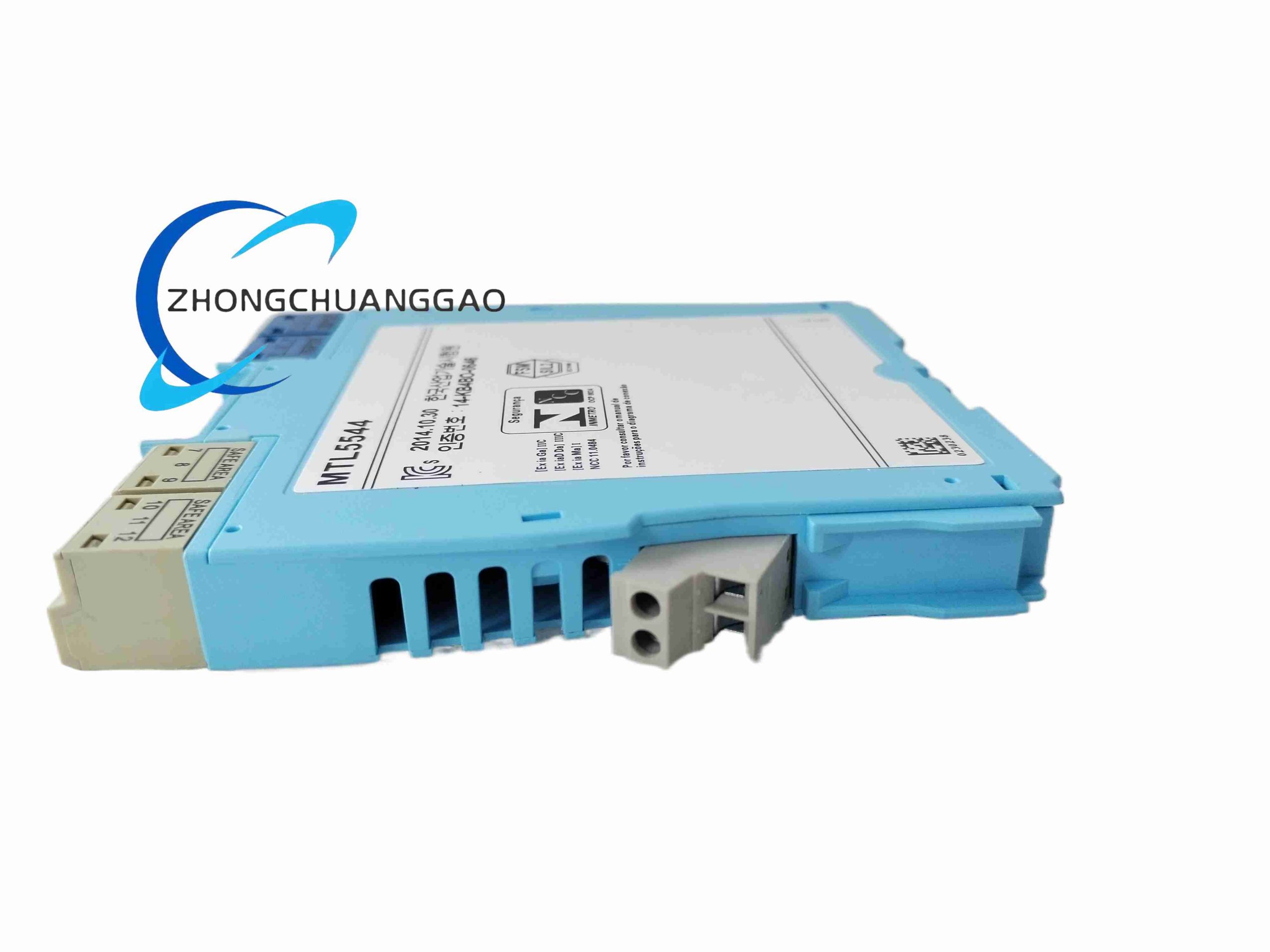
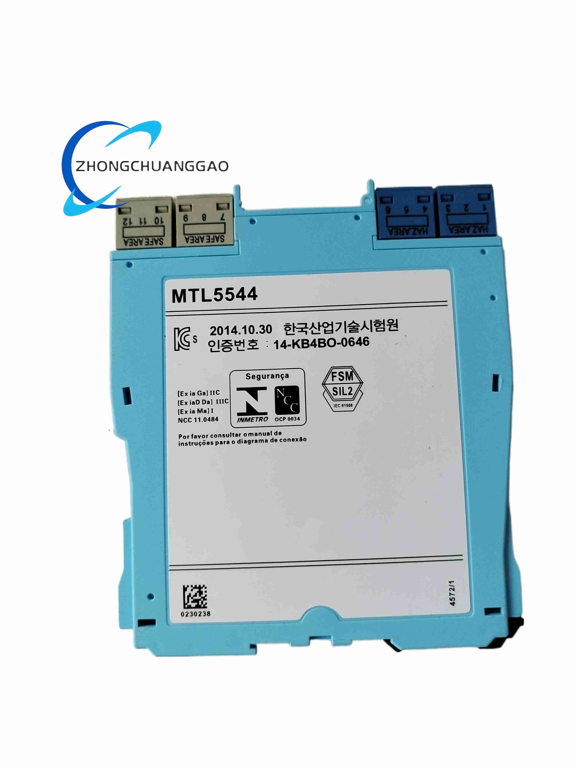
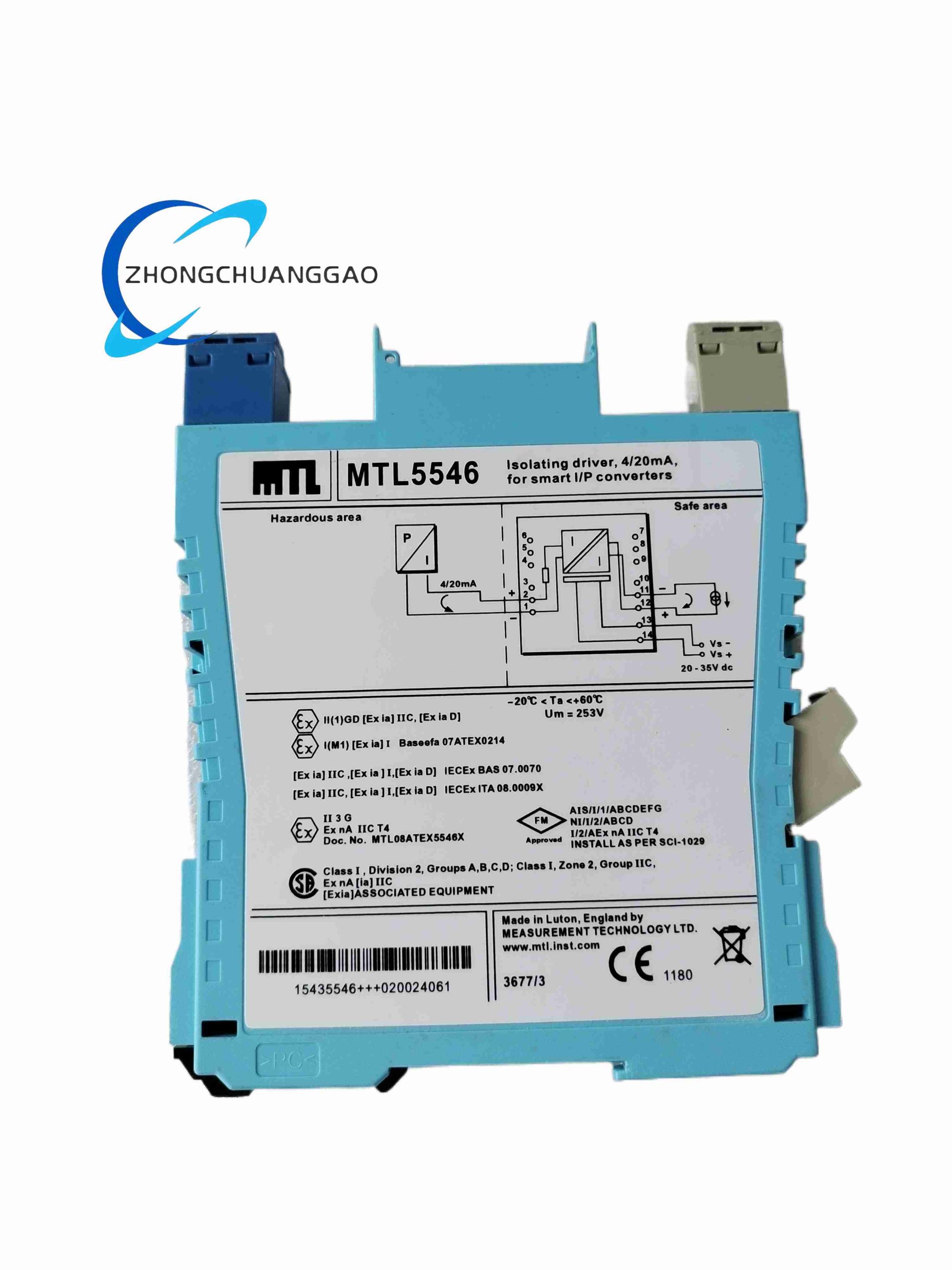
MTL5544 is dual-channel Zener intrinsically safe barrier dedicated to powering 4-wire separate powered field transmitters in Zone 0/1 hazardous areas. It provides isolated regulated loop power for two independent analog measurement circuits simultaneously, delivers galvanic isolation between hazardous field instruments and safe-area DCS input cards, with SIL 2 safety certification for process safety loops.
Description
Core Technical & Performance Parameters
- Explosion Protection Certification: Ex ia IIC T6 Ga, Zone 0 / Zone 1 fully approved
- Channel Count: Dual independent isolated analog input channels
- Supported Field Instrument: Separately powered 4-wire analog transmitters (no internal loop power)
- Maximum Safe Voltage Ui: 28 VDC
- Maximum Safe Current Ii: 93 mA per channel
- Galvanic Isolation Rating: 2500 VAC between hazardous and safe circuits
- Nominal Operating Current Draw: 96mA total at 24V DC cabinet supply
- Operating Ambient Temperature Range: -20°C ~ +60°C
- Safety Integrity Level: SIL 2 capable per IEC 61508 functional safety standard
- Signal Transfer Error: ±0.15% full scale 4-20mA analog signal deviation
Functional Features
- Dual independent isolated channels for two separate 4-wire field transmitters, space-efficient cabinet layout
- Precision Zener barrier energy limiting circuit meeting Ex ia intrinsic safety standards for Zone 0 gas environments
- High galvanic isolation eliminates ground loop noise and common-mode signal distortion
- Low analog signal transfer error for high-precision flow, pressure and temperature measurement
- Compact dual-channel DIN rail module reducing cabinet wiring and component count
- Per-channel reverse polarity protection for field instrument wiring misconnection tolerance
- Wide temperature operating range suitable for industrial outdoor control cabinet deployment
Working Principle
Safe-area 24V input power passes through dual independent isolated power conversion circuits to generate limited-energy intrinsically safe power supply for each 4-wire hazardous field transmitter. Analog 4-20mA measurement signals flow bidirectionally across high-isolation transformer circuitry back to DCS analog input modules. Precision Zener diode, wire-wound resistor and gas discharge tube network clamps peak voltage and fault current entering hazardous field wiring, restricting stored circuit energy below explosive ignition threshold defined in IEC 60079-11.
Material Composition
- Module Housing: Black V0 flame retardant anti-static ABS plastic
- Isolation Components: Dual low-distortion isolation transformers for two independent channels
- Safety Limiting Circuitry: High-stability wire-wound resistors, precision Zener diodes, ceramic surge discharge tubes
- Terminal Blocks: Nickel-plated copper screw terminals, PA66 flame retardant plastic insulation
- Mounting Clips: Zinc-plated spring steel DIN rail fasteners
Structural Characteristics
- Double-width standard 35mm DIN rail module for dual-channel integration
- Two fully separated terminal sections: left hazardous field instrument terminals (Channel 1 & 2), right safe cabinet DCS terminals
- Dual power status LED indicators for visual monitoring of each channel’s loop power operation
- Removable full-width transparent plastic terminal cover to prevent accidental live circuit short-circuit
Installation Requirements
- Install only inside non-hazardous safe-area control cabinets; field cables extend to Zone 0/1 hazardous locations
- Maintain minimum 5mm gap between adjacent MTL series barrier modules for heat dissipation airflow
- Hazardous field instrument wiring must use intrinsically safe certified shielded twisted pair cables
- Cable shielding single-ended grounded at control cabinet protective earth bar; no grounding inside hazardous enclosures
- Torque all terminal screw connections to standardized 0.8 N·m torque to eliminate loose contact resistance drift
- Separate hazardous field wiring cables from high-voltage AC power cables with minimum 25cm physical separation
- Cabinet forced ventilation required if continuous operating ambient temperature exceeds 55°C
Application Scenarios
- Oil & gas Zone 0 wellhead 4-wire high-precision temperature transmitters signal isolation
- Refinery reactor vessel separately powered mass flow meter intrinsic safety barriers
- Chemical batch production Zone 1 analytical transmitter analog signal transmission
- Offshore platform hazardous zone gas chromatography instrument signal isolation
- Pharmaceutical explosion-proof classified production line 4-wire pH / conductivity transmitters
Operation & Maintenance Precautions
- MTL5544 dedicated for 4-wire external-powered transmitters; use MTL4549Y for 2-wire HART loop-powered instruments
- Do not exceed maximum 93mA safe current limit per individual channel
- Annual analog signal transfer accuracy calibration mandatory for SIL 2 safety instrument loops
- Replace module if signal transfer deviation exceeds ±0.3% full scale during routine calibration
- Verify all field wiring cable insulation integrity during yearly shutdown maintenance
- Never connect voltages exceeding 28V DC to hazardous side field instrument terminals
- Avoid installation in cabinet locations exposed to continuous oil mist or corrosive chemical vapor
Reviews
There are no reviews yet.