
Product Short Description
Product Identity
- Brand: DEIF (Danish Marine & Power Generation Protection Control Manufacturer)
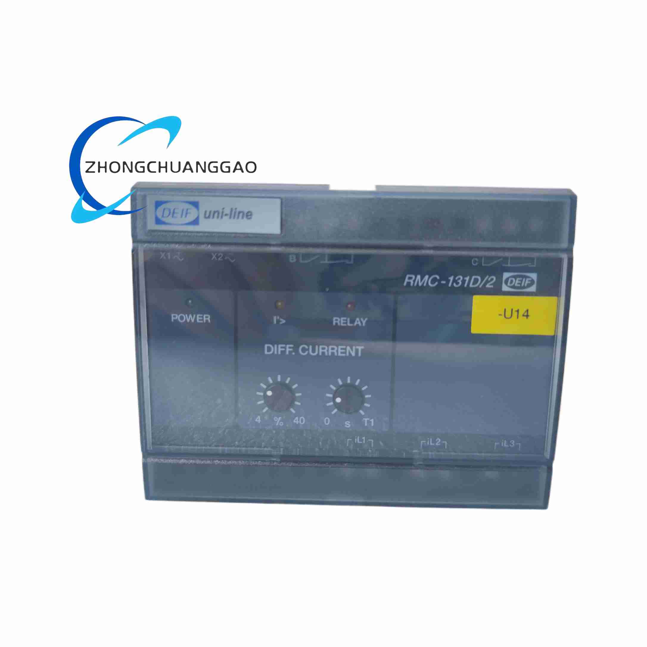
- Model: RMC-131D
- Product Category: Generator Winding Differential Current Protection Relay (ANSI 87 Differential Protection)
Product Overview
RMC-131D is a dedicated three-phase generator differential current protection relay, designed to protect marine generators, land-based diesel generator sets against internal winding short-circuit and leakage current faults, rapidly cutting generator circuit breaker to avoid permanent generator winding burnout damage
Description
Technical Specifications
- Protection Principle: Three-phase RMS differential current measurement; fault judgment based on peak current sampling for ultra-fast response
- Rated Input Current Range (In): 0.3A ~ 4.0A CT secondary current input, field adjustable setting span
- Differential Current Trip Setting Range: 4% ~ 100% In continuously adjustable via front panel potentiometer
- Operating Frequency Range: 40Hz ~ 70Hz (compatible with marine 50Hz/60Hz generator systems)
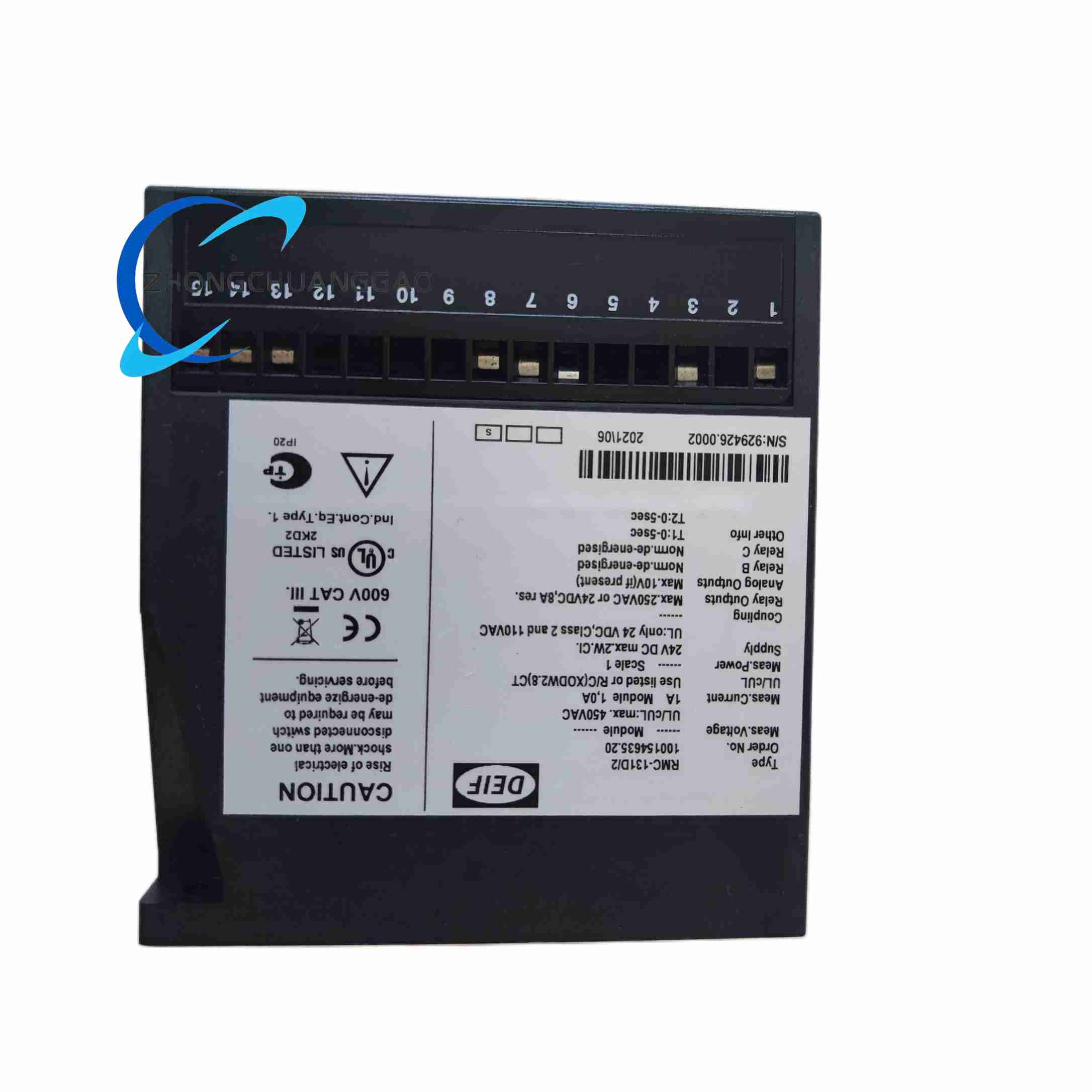
- Relay Output Contact Capacity: Two independent trip relay contact sets; contact rating 250VAC / 24VDC, 8A resistive load
- Fault Response Time: Max 50ms ultra-fast trip action upon differential fault detection
- Hysteresis Parameters: Adjustable trip hysteresis 2% / 6% / 18% of set differential current
- Power Supply: 24VDC industrial/marine standard control power
- Operating Temperature: -25℃ ~ +70℃
- Safety Certification: cUL, IEC 61508 SIL compatible generator protection certification
Functional Features
- Professional ANSI 87 differential protection for generator stator winding internal short-circuit and inter-turn leakage faults
- Dual independent trip relay output contacts, supporting main generator breaker trip signal and fault alarm signal separate output
- Front panel multi-turn potentiometers for precise adjustment of differential trip current threshold and time delay parameters
- Power supply green LED indicator, differential fault red alarm LED indicator for visual fault identification
- Built-in RMS current measurement circuit, stable protection performance under distorted non-sinusoidal generator fault current waveforms
- Anti-transient overcurrent misoperation filtering logic, avoid false tripping during generator startup, load switching transient current surges
Working Principle
The relay receives three-phase secondary current signals from generator current transformers (CT) installed at generator winding input and neutral end. Internal circuit calculates vector difference between incoming and outgoing phase currents (differential current). Under normal generator operating conditions, inflow and outflow phase currents are balanced, differential current value is near zero, relay keeps trip contacts open. When generator stator winding occurs internal short-circuit or inter-turn leakage fault, phase current balance breaks, differential current exceeds user-set trip threshold; relay internal logic triggers trip relay output within 50ms, sending trip signal to generator main circuit breaker to disconnect generator from busbar, preventing severe winding burnout accident.
Structure & Material
- Housing: Standard industrial relay plastic DIN rail enclosure, gray flame-retardant ABS material
- Front Panel: Embedded adjustable potentiometers for parameter setting, dual LED status indicators, printed function parameter scale labels
- Internal Circuit Board: Multi-layer isolated CT signal input PCB, peak/RMS dual-mode current sampling circuits, dual mechanical trip relay assemblies
- Terminals: Screw terminal blocks on module bottom for CT secondary current wiring, 24VDC power supply wiring, trip/alarm relay load wiring
- Mounting: Standard 35mm DIN rail snap mounting in generator control cabinet
Installation Requirements
- DIN rail mounted inside generator protection control cabinet, install away from high-temperature generator cabinet heat sources
- CT secondary wiring must use shielded twisted-pair cables, CT circuit strictly forbidden to open-circuit during operation (risk of high-voltage CT residual voltage hazard)
- All CT cable shielding single-point grounded at protection cabinet terminal strip, prohibit multi-point grounding causing circulating current interference
- Maintain 15mm clearance between adjacent protection relays for heat dissipation
Application Scenarios
- Marine vessel main generator, auxiliary diesel generator winding differential fault protection
- Land-based emergency standby diesel generator set power plant protection
- Offshore wind turbine auxiliary generator, gas turbine generator differential protection
- Hospital, data center critical backup generator safety protection
Operation & Maintenance Notes
- After generator overhaul, perform differential protection injection current test to calibrate RMC-131D trip setting parameters
- Quarterly inspect front panel fault LED records; red fault light indicates generator winding hidden leakage fault requiring generator disassembly inspection
- CT secondary wiring terminals must be checked for looseness every six months; loose CT wiring causes abnormal differential current and false protection tripping
- Never short-circuit or disconnect CT secondary cables while generator is running to avoid dangerous high induced voltage from current transformers
- Keep cabinet ventilation clean to prevent dust accumulation on relay PCB causing signal sampling drift and protection malfunction
-500x500.jpg)
Reviews
There are no reviews yet.