
Product Short Description
Product Overview
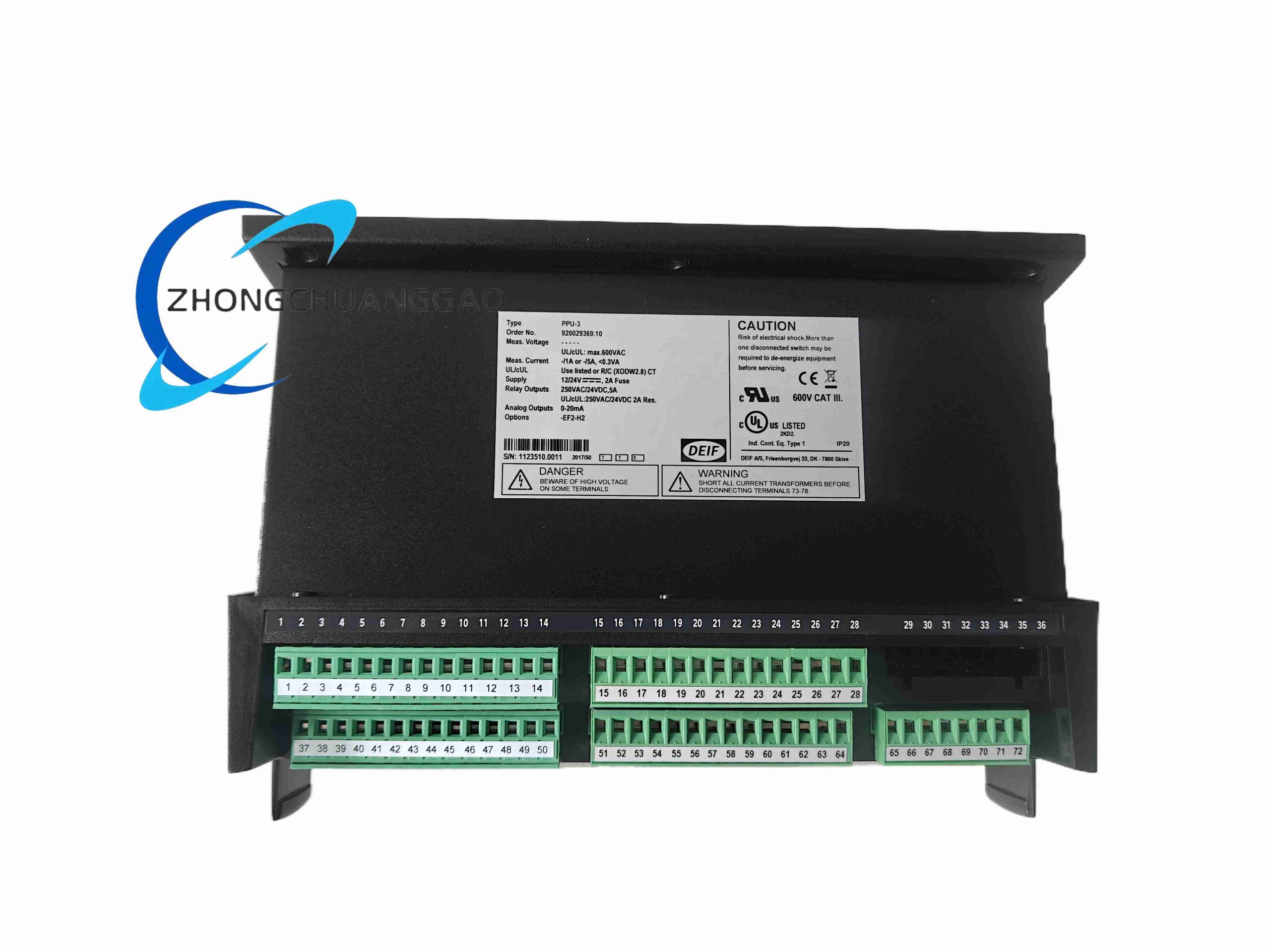
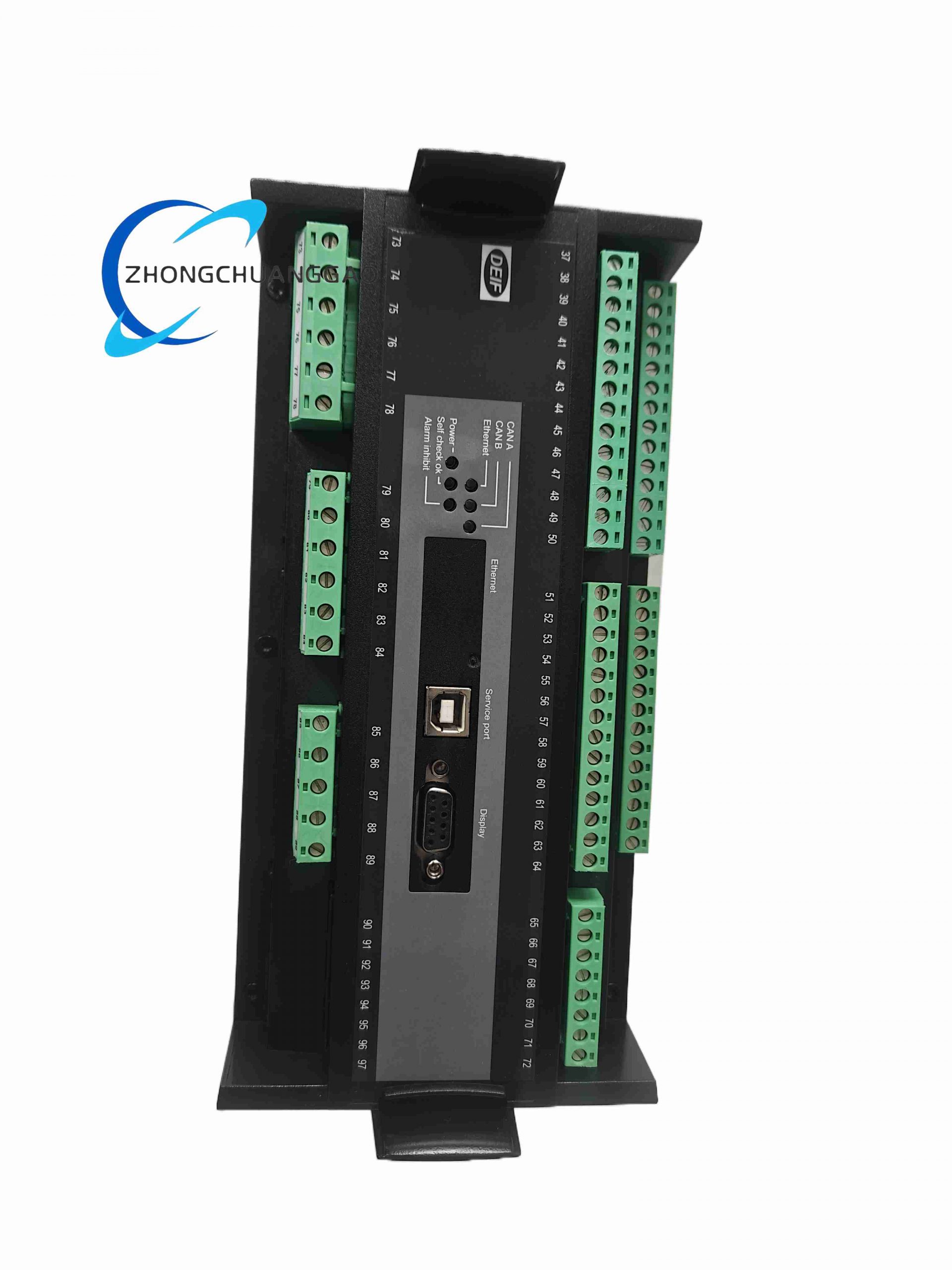
The DEIF PPU-3 is an all-in-one microprocessor-based control unit integrating generator synchronization, parallel load sharing, comprehensive electrical fault protection, and manual/automatic generator operation control, developed under DEIF Multi-Line 2 product series. It is optimized for both land-based stationary generator power stations and marine vessel on-board auxiliary generator systems, supporting single generator standalone operation or multi-unit synchronized parallel grid connection with automatic active/reactive load distribution between generators.
Description
Core Technical Specifications
- Power Supply Input: Dual universal supply options: 24VDC (18–32VDC) or 110/230VAC 50/60Hz; power consumption maximum 12VA
- Three-Phase Measurement System: Galvanically isolated voltage and current measurement channels, accuracy Class 0.5; compatible with standard CT/PT instrument transformers
- Synchronization Control Range: Voltage matching tolerance ±5% nominal, frequency slip range ±0.5Hz, phase angle closing window adjustable 5°–30°
- Load Sharing Performance: Active power sharing error ≤±2% rated generator capacity; reactive power sharing error ≤±3% rated capacity
- Protection Threshold Configurability: All electrical protection trip points, delay timers and alarm logic fully adjustable via front panel HMI
- Communication Interfaces: Dual CAN bus, Modbus TCP Ethernet, RS485 Modbus RTU; supports DEIF remote monitoring platform and third-party SCADA
- Local HMI Hardware: Backlit 128×64 graphical LCD display, tactile membrane function keys, multi-color LED status indicators (Run, Sync, Alarm, Trip)
- Digital I/O Allocation: 12 digital input channels, 8 relay output channels (5A resistive contact rating) for breaker control, alarm indication and auxiliary interlocks
- Analog Regulation Outputs: 0–10V / 4–20mA dual analog outputs for engine governor speed control and AVR voltage regulation
- Environmental Ratings: Operating temperature -20°C ~ +70°C; storage -40°C ~ +85°C; relative humidity 5–95% non-condensing
- Mechanical Compliance: IEC 60068 vibration 5G, shock 10G; marine type approval DNV, LR, ABS for shipboard installation
- Physical Dimensions: Front panel 144mm × 144mm; mounting cutout 138mm × 138mm; depth behind panel 58mm; weight 650g
- Protection Grade: Front face IP54; rear wiring compartment IP20
- Certifications: CE, UL, marine classification society certifications, IEC 60255 protection relay standard
Function & Performance Features
- Fully automatic synchronization sequence: detects voltage/frequency/phase difference, adjusts engine speed and generator excitation, closes circuit breaker only when all sync conditions are satisfied
- Static and droop-based load sharing algorithm for parallel generator groups, automatically balancing real and reactive power after breaker closure
- Complete tiered electrical protection suite with selectable alarm-only or full trip action: overvoltage, undervoltage, overfrequency, underfrequency, reverse active power, reverse reactive power, overcurrent, short-circuit instantaneous trip, earth leakage fault, CT open-circuit detection
- Dual analog control outputs independently adjust diesel engine governor speed and generator automatic voltage regulator excitation for precise frequency and voltage matching
- Separate manual / auto operating modes; manual fine-tuning knobs for on-site technician synchronization testing
- Comprehensive event log storage: up to 200 historical fault, sync and breaker operation records with timestamp for troubleshooting root cause analysis
- Anti-islanding protection function for grid-parallel generators, immediately tripping generator breaker if mains grid power is lost
- Multi-language graphical HMI interface, supports unit parameter cloning via USB memory stick for fast multi-generator fleet commissioning
- Built-in test simulation mode to verify all protection trips, sync logic and relay outputs without live generator power
- CAN bus multi-drop communication links multiple PPU-3 units together for master-slave parallel operation of up to 16 generator sets
Working Principle
The unit continuously samples three-phase generator voltage and CT secondary current signals through isolated measurement circuits. Internal microcontroller compares generator parameters against busbar grid parameters to calculate voltage, frequency and phase deviation. Analog output signals adjust engine fuel governor and excitation AVR to eliminate deviation until synchronization window requirements are met, then sends relay signal to close generator circuit breaker. After paralleling, real-time load calculation distributes active and reactive load evenly across all parallel generators via cross-connected CAN bus load share signals. Measurement channels constantly monitor for abnormal electrical conditions; once any parameter crosses user-set protection threshold, internal logic triggers timed alarm or instantaneous breaker trip while storing fault event data to non-volatile flash memory. All local operator commands via front panel keys and remote SCADA commands via Ethernet/RS485 are processed with priority interlock safety logic to prevent unsafe breaker operation.
Material & Structural Composition
- Front panel housing: Flame-retardant reinforced ABS plastic with dust/waterproof sealing gasket to achieve IP54 front protection
- Internal main PCB: Multi-layer FR4 industrial circuit board with full conformal coating to resist marine salt mist and cabinet condensation
- Membrane control interface: Wear-resistant silicone rubber key mat with printed overlay, UV-resistant ink for long service life under high light exposure
- Terminal wiring block: Screw-clamp PA66 flame retardant terminals separated into power, measurement, communication and control signal zones
- Core electronic hardware: Isolation transformers for voltage/current sensing, wide-temperature LCD driver chips, surge suppression TVS arrays on all external wiring ports
- Mounting hardware: Stainless steel panel clamping brackets with anti-loosening springs to withstand vibration on marine vessels and mobile generator trailers
Installation Requirements
- Panel cutout mounting only; flush install on generator control cabinet front door, maintain minimum 100mm clearance behind panel for wiring and heat dissipation
- CT secondary wiring must use twisted shielded cable; strictly avoid open-circuit CT terminals at any time during wiring maintenance
- Separate high-power breaker control wiring and low-level measurement signal wiring with minimum 40mm routing distance to reduce induced electrical noise
- All measurement, communication and power cable shielding must connect to cabinet dedicated protective earth bar with copper wire ≥1.5mm² cross-section
- Tighten terminal block screws to torque 0.7–0.9 N·m to prevent thermal loosening under continuous mechanical vibration
- For marine vessel installation, mount dehumidifier equipment inside control cabinet to eliminate salt fog condensation on PCB surface
- Complete full synchronization and protection simulation test after installation before connecting live generator and grid power
Typical Application Scenarios
- Marine cargo ship, yacht and offshore platform auxiliary generator parallel control panels
- Land-based industrial backup generator power stations with multiple diesel generator sets
- Hospital, data center, commercial building critical standby power distribution systems
- Mining site mobile multi-generator parallel power supply containers
- Renewable hybrid power systems (diesel generator + solar storage grid stabilization control)
Mandatory Operation & Maintenance Precautions
- Disconnect all generator mains power and control supply before removing the unit from cabinet panel for inspection or replacement
- Wear anti-static wristband when accessing rear PCB terminals or connecting USB parameter cloning sticks
- Quarterly inspection of front panel sealing gasket for cracks or degradation to maintain IP54 dust and moisture protection
- Semi-annually clean LCD screen and membrane keys with dry microfiber cloth; never use corrosive chemical cleaners
- Backup all generator protection and synchronization parameters to USB storage before firmware upgrade or unit replacement
- Never short-circuit CT secondary measurement terminals; this will disable overcurrent protection and risk equipment damage
- If parallel load imbalance occurs, first verify CAN bus wiring continuity and shield grounding integrity before recalibrating load share parameters
Reviews
There are no reviews yet.