
Product Short Description
Product Brief
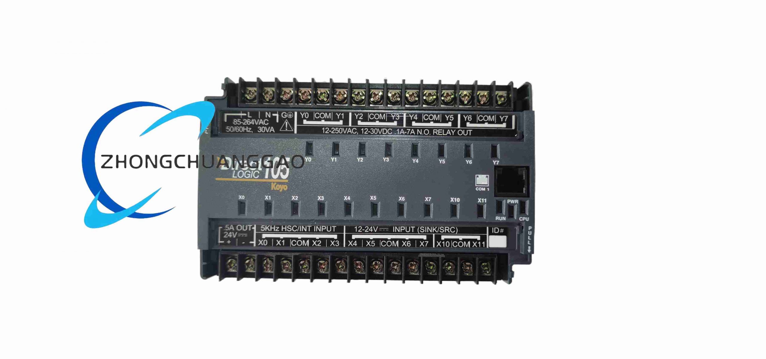
F1-130DR is a relay output type miniature integrated PLC launched by Mitsubishi Electric, specially designed for small-scale discrete automation control logic, integrating power supply, CPU, digital input and relay output terminals in a single compact housing, widely matched with low-power automatic machinery and simple process control equipment.
Model Series
F1 Series Compact Integrated Micro PLC, model specification F1-130DR
Description
Technical Specifications
- Main Control Processor: 8-bit industrial dedicated logic CPU
- Program Storage Capacity: 1000 steps of ladder logic program memory
- I/O Allocation Total: 30 points integrated fixed I/O
- Digital Input Points: 16 points DC 24 VDC sink input
- Digital Output Points: 14 points mechanical relay contact output
- Rated Power Supply Input: AC 100–240 VAC 50/60 Hz universal alternating current
- Relay Output Single Point Rated Load: Resistive load 2 A / 250 VAC; Inductive load 0.5 A / 250 VAC
- Basic Instruction Execution Speed: 12 μs per basic logic instruction
- Communication Interface: On-board RS422 programming port for handheld programmer or upper computer connection
- Operating Ambient Temperature Range: 0 °C to +55 °C
- Storage Temperature Range: -20 °C to +70 °C
- Protection Class: IP20 overall housing, suitable for indoor cabinet installation
- Compliance Standards: IEC 61131-1, IEC 61010 industrial control equipment safety standards
Functional Features
- Integrated fixed 30-point I/O structure without external expansion modules, ready for direct wiring deployment
- Complete basic ladder logic instruction set: contact logic, timer, counter, shift register, comparison operation
- Built-in 64 internal auxiliary relays, 32 timers (0.1 s–3200 s adjustable timing range), 32 counters
- Hardware high-speed counting function, maximum input pulse frequency 2 kHz for simple positioning signal collection
- Internal latch relay register for power-off retention of key equipment state signals
- RS422 dedicated programming interface supports offline program upload/download and online real-time monitoring
- Built-in power surge suppression circuit to resist instantaneous voltage fluctuation of factory power grid
- CPU hardware self-diagnosis function, with front panel LED fault indicator for program error, power loss and I/O short circuit
- Simple analog value comparison function realized through external voltage divider matching input terminals
- Ladder logic program password lock function to prevent unauthorized modification of control logic
Performance Parameters
- Relay output mechanical service life under rated resistive load: 10,000,000 switching cycles
- Power-off retention data storage time: ≥ 10 years via built-in lithium backup battery
- Timer timing accuracy: ±0.01 s full timing range
- High-speed counter pulse sampling accuracy: ±1 pulse error within rated frequency range
- Front panel LED indication response delay: ≤ 10 ms after I/O signal change
- Program download transmission speed: 9600 baud fixed communication rate
Material Composition
- Outer housing: Flame retardant V0 grade ABS engineering plastic with anti-static treatment
- Main control PCB: FR4 flame retardant printed circuit board with EMC noise reduction circuit
- Input signal optocoupler isolation components: High-speed photoelectric isolation chips with wide temperature resistance
- Output mechanical relay: Silicon steel magnetic core, silver alloy contact anti-arc material
- Terminal block assembly: Glass fiber reinforced PA66 plastic shell, tin-plated copper conductive terminals
- Backup power supply: CR2032 industrial grade lithium button cell for power-off data retention
Structural Characteristics
- Standard 35 mm DIN rail mounting structure, overall dimension: 180 mm (Width) × 90 mm (Height) × 85 mm (Depth)
- Front panel layout: Power status LED, CPU running LED, fault alarm LED, input/output status indicator lamp group
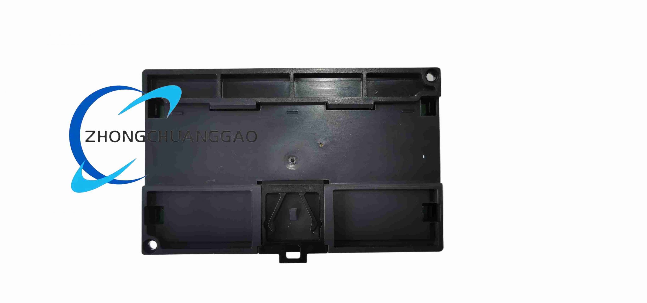
- Rear side fully separated terminal area: AC power supply terminals, 24 VDC input signal terminals, relay output load terminals, RS422 programming port
- Integrated elastic DIN rail locking buckle, automatic clamping after sliding onto standard mounting rail
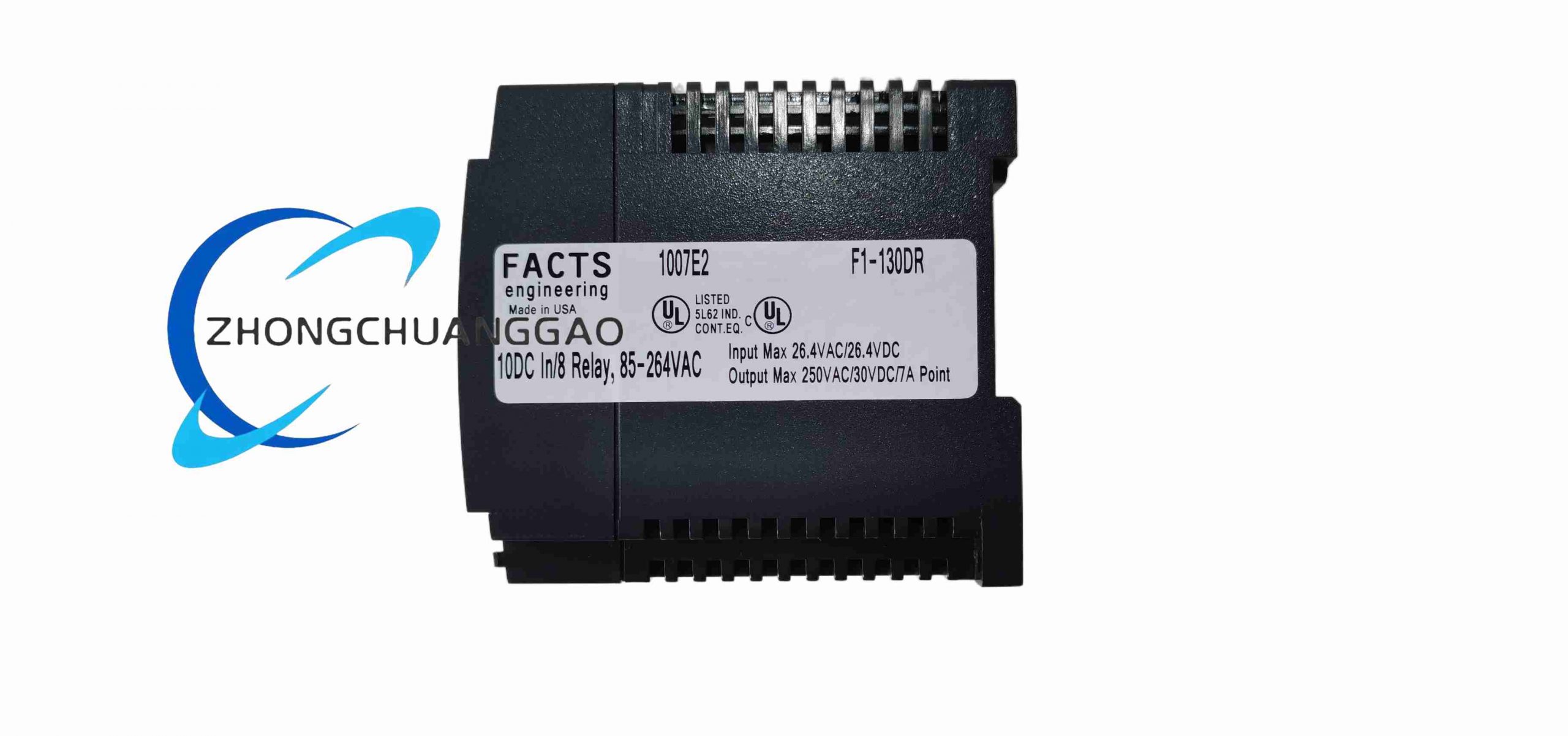
- Ventilation heat dissipation slits reserved on the top and bottom of the shell for passive heat dissipation of internal circuits
- Independent wiring partition between high-voltage AC power terminals and low-voltage DC signal terminals to avoid cross interference
Working Principle
AC 100–240 VAC input passes through the internal EMI filter and rectifier circuit to convert into stable isolated DC working power supply for the CPU core, input optocoupler circuit and output relay drive circuit. 24 VDC digital input signals are converted into isolated digital logic levels through optocouplers and transmitted to the main control CPU for cyclic scanning reading. The CPU executes solidified ladder logic programs step by step according to fixed scanning cycles, calculates the logical state of each output point, and drives the corresponding mechanical relay to pull in or disconnect contacts to control external loads such as contactors, indicator lights and solenoid valves. Built-in timers and counters complete timing, counting and interlock logic operations relying on CPU internal registers; power-off latch registers maintain equipment operating state through lithium battery power supply when mains power fails. The RS422 communication port realizes bidirectional data exchange with programming equipment to complete program writing, online monitoring and fault diagnosis. The hardware self-diagnosis module continuously detects CPU operation, power supply voltage and I/O circuit short-circuit faults, and lights the front fault LED indicator when abnormal conditions occur.
Advantage Highlights
- All-in-one integrated 30-point I/O design, no additional expansion modules required, reducing cabinet wiring space and procurement cost
- Fast basic instruction execution speed to meet real-time control requirements of small automation equipment
- Built-in complete timer, counter and auxiliary relay resources, sufficient for simple assembly, conveying and packaging machine logic
- Mechanical relay output supports direct driving of AC low-power loads without intermediate relay transfer
- Wide-range universal AC power supply adapts to industrial power grid voltage differences in various regions
- DIN rail compact structure is convenient for quick installation and disassembly in standard electrical control cabinets
- Built-in lithium battery realizes long-term power-off data retention without external backup power supply
- Independent RS422 programming port supports handheld programmer and upper computer dual debugging methods
Applicable Industries
Small automated packaging machinery, light-duty conveyor lines, water treatment small dosing control equipment, agricultural automatic processing machines, small injection molding auxiliary equipment, ventilation fan and pump group interlock control, laboratory test automation equipment, food small filling machinery, printing auxiliary transmission equipment
Installation Requirements
- Install on standard 35 mm DIN rail inside indoor closed electrical cabinet, ambient humidity controlled below 90% non-condensing
- Maintain a minimum clearance of 40 mm above and below the PLC shell to ensure passive heat dissipation air circulation
- Separate high-current relay output load wiring and low-voltage DC input signal wiring by a minimum distance of 8 cm
- The AC power input terminal must be connected with an independent miniature circuit breaker for short-circuit overload protection
- Install surge absorption diodes or RC absorption loops at both ends of inductive loads connected to relay output terminals
- Ground the cabinet metal mounting rail to the equipment protective ground bus with 2.5 mm² copper wire
- Avoid installing the PLC in the same cabinet with high-frequency inverters without isolation shielding plates
Operation Precautions
- Replace the built-in lithium backup battery every 5 years to prevent power-off program and register data loss
- The relay output points are prohibited from exceeding the rated load current to avoid contact ablation and permanent damage
- Conduct full program backup to programming equipment before modifying ladder logic to prevent program loss
- Do not operate the equipment when the ambient temperature exceeds +55 °C; install forced cooling fans for high-temperature cabinet environments
- Disconnect the AC main power supply and wait for 2 minutes for internal circuit capacitor discharge before disassembling wiring terminals
- Prevent metal debris, dust and conductive liquid from entering the ventilation slits of the shell to avoid internal short-circuit faults
- Execute full I/O point manual test after each program modification to verify the correctness of control logic output
- Do not connect inductive loads without absorption circuit directly to relay output terminals for long-term continuous operation
Reviews
There are no reviews yet.