Product Short Description
Product Introduction:
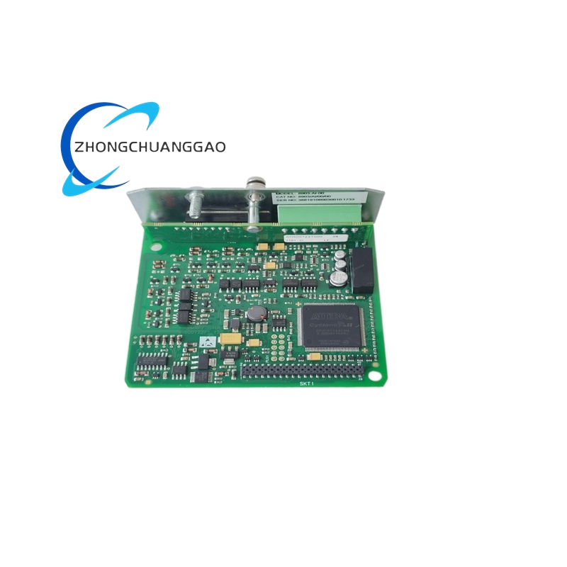
The Communication 8903-AI-00 is a DIN rail-mounted, 4-channel analog input acquisition module from the CEC 8900 series. It accepts 4 independent analog inputs and converts them to 16-bit digital values for transmission to a host controller via RS-485 (Modbus RTU) or Ethernet/IP communication. Each channel is individually configurable for input type (4–20 mA or 0–10 VDC), engineering unit scaling, filtering, and alarm thresholds.
Description
Technical Specifications:
- Model Number: 8903-AI-00
- Manufacturer: Communication Electronics Corporation (CEC)
- Series: 8900 Series
- Module Type: 4-Channel Analog Input Module
- Input Channels: 4 independent channels (CH1–CH4)
- Input Type: 4–20 mA (2-wire loop powered) or 0–10 VDC (3-wire)
- Resolution: 16-bit (65,536 counts)
- Accuracy: ±0.1% of full scale (at 25°C)
- Sampling Rate: 10 samples per second per channel (40 Hz total)
- Isolation: 1500 VDC galvanic isolation (channel-to-bus)
- Communication: RS-485 (Modbus RTU) and Ethernet/IP (via option card)
- Power Supply: 24 VDC (18–32 VDC range)
- Power Consumption: <2.5 W
- Operating Temperature: -20°C to +70°C (-4°F to +158°F)
- Storage Temperature: -40°C to +85°C (-40°F to +185°F)
- Humidity: 5% to 95% (non-condensing)
- Mounting: DIN rail (EN 60715, 35 mm)
- Dimensions (W×H×D): Approximately 120 × 90 × 65 mm (4.72 × 3.54 × 2.56 in)
- Weight: Approximately 250 g (0.55 lbs)
Functional Features:
- 4 Independent Input Channels: Each channel accepts 4–20 mA or 0–10 VDC; channels are fully isolated from each other
- Programmable Scaling: Each channel can be scaled to any engineering unit (PSI, °C, °F, GPM, %, etc.) via host configuration
- 16-Bit Resolution: Provides 65,536 discrete steps across the full input range; detects changes as small as 0.003% of full scale
- Programmable Low/High Alarms: Each channel has 2 configurable alarm setpoints with latching or non-latching behavior
- Digital Filtering: Adjustable moving average filter (1 to 100 samples) eliminates noise from long cable runs
- Loop-Powered 2-Wire Support: CH1–CH4 support 2-wire 4–20 mA loop power; no separate power supply needed for transmitters
- Cold Junction Compensation (CJC): Built-in CJC for thermocouple input variants (on select models)
- LED Channel Indicators: Individual green LEDs for each channel indicating active signal; red LEDs for alarm conditions
- Modbus RTU Slave: Responds to Function Code 03 (Read Holding Registers) and Function Code 04 (Read Input Registers)
- Ethernet/IP Option: Available with 8900-ETH option card for native Ethernet/IP communication (explicit messaging)
- DIP Switch Configuration: Channel input type and address set via 8 DIP switches on the module
- Fail-Safe Output: On communication loss, analog outputs (if equipped) hold last valid value or go to configured fail-safe
Performance Parameters:
| Parameter | Value |
|---|---|
| Number of Channels | 4 (CH1–CH4) |
| Input Signal Type | 4–20 mA (2-wire) or 0–10 VDC (3-wire) |
| Input Impedance (Voltage Mode) | >1 MΩ |
| Input Impedance (Current Mode) | 250 Ω burden resistor (internal, switchable) |
| Resolution | 16-bit (65,536 counts) |
| Accuracy | ±0.1% of full scale (25°C) |
| Linearity | ±0.05% of full scale |
| Sampling Rate | 10 Hz per channel (40 Hz aggregate) |
| Isolation Voltage | 1500 VDC (channel-to-bus, 1 minute) |
| Common Mode Rejection | >120 dB at 50/60 Hz |
| Normal Mode Rejection | >80 dB at 50/60 Hz |
| Alarm Response Time | <100 ms |
| Communication Protocol | Modbus RTU (RS-485), Ethernet/IP (option) |
| Baud Rate (RS-485) | 9600, 19200, 38400, 57600, 115200 bps |
| Supply Voltage | 24 VDC (18–32 VDC) |
| Supply Current | <105 mA at 24 VDC |
| Power Dissipation | <2.5 W |
| Operating Temperature | -20°C to +70°C |
| Storage Temperature | -40°C to +85°C |
| Humidity | 5% to 95% (non-condensing) |
| Vibration | 5 g, 10–500 Hz (per IEC 60068-2-6) |
| Shock | 30 g, 11 ms half-sine (per IEC 60068-2-27) |
| MTBF | >100,000 hours |
| Enclosure Rating | IP20 (indoor use only) |
Material Composition:
- Housing: UL 94V-0 rated flame-retardant polycarbonate/ABS blend (dark gray)
- PCB: FR-4 fiberglass epoxy laminate with conformal coating (mil-spec)
- Isolation Barrier: Optocouplers (Si86xx series) with 1500 VDC isolation rating
- ADC Chip: Texas Instruments ADS1115 (16-bit, 4-channel, I2C-compatible SAR ADC)
- Terminal Blocks: Tin-plated phosphor bronze screw terminals (5.08 mm pitch)
- Connectors: Phoenix Contact 3.5 mm pitch pluggable terminal blocks
- DIN Rail Clip: Zinc-plated spring steel with locking tab
- LEDs: High-brightness red/green LEDs (20 mcd, 20° viewing angle)
- Internal Wiring: 22–26 AWG stranded tinned copper with PVC insulation
- Gaskets: Silicone rubber seal around front panel (IP20 rated)
- Label: Laser-etched aluminum nameplate with model number, serial number, and ratings
Structural Features:
- DIN Rail Module: Single-width design mounts on standard 35 mm top-hat DIN rail (EN 60715)
- Front Panel: 4 channel LED indicators (green = normal, red = alarm), 8 DIP switches for address/configuration, 2 status LEDs (Power, Communication)
- Rear Panel: DIN rail clip, 4× analog input terminal blocks (CH1–CH4), RS-485 terminal block (A+, B−, GND), 24 VDC power terminal block, Ethernet/IP option card slot (if equipped)
- Terminal Blocks: 5.08 mm pitch, 3-position screw terminals per channel; rated for 14–22 AWG wire
- DIP Switch Bank: 8 switches (SW1–SW8): SW1–SW2 = Module Address (0–63), SW3–SW4 = Baud Rate, SW5–SW6 = Input Type, SW7–SW8 = Alarm Mode
- Option Card Slot: Right-side edge connector for 8900-ETH Ethernet/IP card or 8900-CAN CAN bus card
- Ventilation: 2 side ventilation slots for passive cooling; no fan required
- Dimensions: 120 mm (W) × 90 mm (H) × 65 mm (D) excluding DIN rail clip
- Weight: 250 g (0.55 lbs)
Working Principle:
The Communication 8903-AI-00 receives analog signals (4–20 mA or 0–10 VDC) from field transmitters on 4 independent input channels (CH1–CH4). Each channel passes through a 250 Ω burden resistor (current mode) or a voltage divider (voltage mode), converting the signal to a voltage proportional to the measured process variable. The signal is filtered by a programmable digital moving average filter (1–100 samples) to reject high-frequency noise. The filtered signal is then fed to a 16-bit successive approximation register (SAR) analog-to-digital converter (ADC), which samples at 10 Hz per channel and outputs a 16-bit digital value (0–65,535). Each digital value is scaled by the host controller using the programmed engineering unit conversion factors (e.g., 4 mA = 0 PSI, 20 mA = 100 PSI). The scaled values are stored in Modbus holding registers and made available to the host via RS-485 (Modbus RTU) or Ethernet/IP (explicit messaging). The galvanic isolation barrier (1500 VDC optocouplers) separates the analog input circuitry from the digital communication circuitry, preventing ground loops and voltage transients from damaging the host controller. Each channel has 2 configurable alarm setpoints (high and low); when the measured value crosses a setpoint, the corresponding red LED illuminates and the alarm status is reported in the Modbus register map.
Advantages and Highlights:
- 4-Channel Isolation: Each of the 4 channels is individually isolated at 1500 VDC; a fault on one channel does not affect the others
- 16-Bit Resolution: 65,536 discrete steps provide superior resolution compared to 12-bit (4096 steps) modules
- Dual Input Type Support: Each channel accepts 4–20 mA or 0–10 VDC; no hardware changes required
- Programmable Alarms: 2 alarm setpoints per channel with latching/non-latching selection
- Digital Filtering: Adjustable moving average filter (1–100 samples) eliminates noise from long cable runs
- 2-Wire Loop Power: Supports loop-powered transmitters; no separate 24 VDC needed for field devices
- Dual Communication: RS-485 Modbus RTU + Ethernet/IP option for flexible system integration
- DIP Switch Configuration: No software required for address and basic setup; change settings on the fly
- Wide Temperature Range: -20°C to +70°C; suitable for outdoor enclosures with NEMA 4X housing
- Low Power: <2.5 W; minimizes heat generation in dense DIN rail panels
- MTBF >100,000 Hours: Designed for 10+ years continuous operation in industrial environments
- CEC Legacy Compatibility: Pin-compatible with legacy CEC 8900 series modules; drop-in replacement
Applicable Industries:
- Oil and Gas: Pressure transmitters, flow meters, level sensors on wellheads and pipeline stations
- Water and Wastewater: Flow measurement, level monitoring, chlorine dosing control
- HVAC and Building Automation: Temperature sensors, humidity transmitters, CO2 sensors
- Manufacturing: Process variable monitoring on CNC machines, injection molding, packaging lines
- Power Generation: Boiler pressure, condenser level, turbine vibration monitoring
- Food and Beverage: Temperature monitoring in pasteurizers, fermenters, and storage tanks
- Pharmaceutical: Cleanroom environmental monitoring (temperature, humidity, pressure differential)
- Mining: Ventilation airflow, slurry level, conveyor belt speed monitoring
- Pulp and Paper: Stock consistency, paper machine temperature, dryer exhaust monitoring
- Chemical Processing: Reactor temperature, tank level, chemical flow rate monitoring
Model Series:
| Model Number | Channels | Input Type | Communication | Special Feature |
|---|---|---|---|---|
| 8903-AI-00 | 4 | 4–20 mA / 0–10 VDC | RS-485 Modbus RTU | Standard model (current) |
| 8903-AI-01 | 4 | 4–20 mA / 0–10 VDC | Ethernet/IP | Ethernet native (no option card) |
| 8903-AI-02 | 8 | 4–20 mA / 0–10 VDC | RS-485 Modbus RTU | 8-channel variant |
| 8903-AO-00 | 4 | 4–20 mA output | RS-485 Modbus RTU | 4-channel analog output module |
| 8903-DI-00 | 8 | 24 VDC dry contact | RS-485 Modbus RTU | 8-channel digital input module |
| 8903-DO-00 | 8 | 24 VDC relay output | RS-485 Modbus RTU | 8-channel digital output module |
| 8903-RTD-00 | 4 | PT100 / PT1000 RTD | RS-485 Modbus RTU | 4-channel RTD input with CJC |
| 8903-TC-00 | 4 | Type J, K, T, E, S, R thermocouple | RS-485 Modbus RTU | 4-channel thermocouple input with CJC |
| 8903-AI-R-00 | 4 | 4–20 mA / 0–10 VDC | RS-485 Modbus RTU | Redundant dual-channel variant |
| 8903-AI-H-00 | 4 | 4–20 mA / 0–10 VDC | RS-485 Modbus RTU | High-temperature variant (-40°C to +85°C) |
Installation Requirements:
- Mounting: 35 mm DIN rail (EN 60715) in a control panel or dedicated enclosure
- Enclosure Rating: Minimum NEMA 1 (indoor) or NEMA 4X (outdoor/washdown) for outdoor installations
- Ambient Temperature: Maintain enclosure interior at -20°C to +55°C for optimal accuracy
- Clearance: Minimum 25 mm (1 in) clearance above and below module for ventilation
- Power Supply: 24 VDC regulated, filtered, with maximum ripple <100 mV peak-to-peak
- Grounding: Connect chassis ground to building equipment grounding conductor; ground resistance <1 Ω
- Cable Routing: Separate analog signal cables from power cables (24 VDC) by minimum 100 mm (4 in)
- Shield Grounding: Ground cable shields at the module end only (single-point grounding) to avoid ground loops
- Wire Gauge: Use 18–22 AWG for analog signal wires; 14–18 AWG for 24 VDC power wires
- Terminal Torque: Tighten all terminal screws to 0.5 Nm (4.4 in-lb); re-torque after 72 hours
- DIP Switch Setting: Set module address (SW1–SW2) to a unique value (1–63); avoid address conflicts on the RS-485 bus
- Bus Termination: Install 120 Ω termination resistor at both ends of the RS-485 bus (per Modbus specification)
- Baud Rate Matching: Ensure all devices on the RS-485 bus use the same baud rate (set via SW3–SW4)
Usage Precautions:
- Do not exceed 32 VDC supply voltage: Overvoltage permanently damages the ADC and isolation barrier
- Do not reverse polarity: 24 VDC must be connected with correct polarity; reverse polarity protection is not provided
- Do not exceed 25 mA per channel: Input current above 25 mA damages the internal burden resistor and ADC
- Do not exceed 12 VDC per channel (voltage mode): Input voltage above 12 VDC damages the input divider network
- Do not connect voltage and current inputs simultaneously on the same channel: This causes a short circuit across the burden resistor
- Do not disconnect field transmitters while the module is powered: Sudden open-circuit on a 4–20 mA input triggers a fault condition; always power down before disconnecting
- Do not exceed 64 modules on a single RS-485 bus: The Modbus RTU protocol supports a maximum of 64 slave addresses; use a repeater for larger networks
- Do not mix shielded and unshielded cables on the same bus: Unshielded cables act as antennas and introduce noise into the system
- Perform insulation test before first use: Measure >100 MΩ at 500 VDC between all input terminals and chassis ground
- Calibrate annually: Send module to CEC authorized service center for recalibration to maintain ±0.1% accuracy
- Do not operate above 70°C ambient: Exceeding the operating temperature range voids warranty and degrades ADC accuracy
- Do not paint the housing: Paint covers ventilation slots and increases operating temperature; voids UL listing
- Use only CEC-specified cables: Analog signal cable must be shielded twisted pair (STP); do not use unshielded cable
- Record DIP switch settings: Document all DIP switch configurations (address, baud rate, input type) for future reference
- Export event log monthly: Use Modbus polling to read alarm registers; document all alarm events for regulatory compliance
- Replace after 10 years: Even if functional, ADC drift and capacitor aging reduce accuracy; replace per CEC lifecycle recommendation
- Do not install in explosive atmospheres: The module is rated IP20 (indoor only); use an intrinsically safe barrier in hazardous locations
Reviews
There are no reviews yet.