
Product Short Description
Product Overview
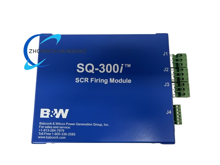
SQ-300i series is the third-generation hybrid automatic voltage control core controller independently developed by Babcock & Wilcox (B&W), dedicated to high-voltage transformer rectifier (T/R) sets of industrial electrostatic precipitators for flue gas dust removal. Model 8700700-004 and 8700700-006 differ only in factory pre-calibrated parameter sets for different T/R power ratings; the hardware mechanical structure, circuit design and core functional logic are completely identical.
Description
Core Technical Specifications
- Control Object Compatibility: Single-phase T/R rectifier set (0–100kV secondary voltage), three-phase low ripple T/R rectifier set (0–120kV secondary voltage)
- Control Input Power Supply: 24 VDC industrial control power supply
- Analog Signal Input Channels: 4 channels 0–10VDC voltage signal (flue gas temperature, dust concentration, inlet/outlet pressure differential)
- Analog Control Output Channels: 2 channels 4–20mA current signal (SCR thyristor firing angle regulation for T/R primary voltage control)
- Digital Switch Inputs: 8-channel dry contact input (door interlock, high-voltage cabinet safety lockout, fan running status feedback)
- Digital Relay Outputs: 6-channel relay contact output (high-voltage trip alarm, spark over-limit alarm, over-temperature fault alarm, remote fault signal transmission)
- Communication Interfaces: RS485 Modbus RTU standard industrial bus, compatible with B&W SQControl upper computer monitoring software
- Response Speed: Spark breakdown detection and suppression response time < 1ms
- Operating Ambient Temperature: -20°C ~ +60°C
- Protection Enclosure Rating: IP65 front panel, IP30 internal circuit compartment
- Overall Dimensions: 263 mm (W) × 58 mm (D) × 280 mm (L)
- Net Weight: 4.3 kg
- Certifications: CE, UL, ISO 14001 environmental compliance certification
Material Composition & Structural Features
- Outer Control Enclosure: Cold-rolled steel sheet welded enclosure with epoxy anti-rust electrostatic spraying surface; front panel transparent tempered glass observation window with waterproof rubber sealing gasket
- Internal Circuit Board: Multi-layer high-Tg FR-4 PCB with double-sided conformal acrylic coating to resist flue gas sulfur-containing corrosive gas and high humidity industrial environment
- Power & Control Semiconductors: Industrial-grade SCR thyristor drive chips, high-speed analog operational amplifiers, multi-channel optocoupler signal isolation devices, surge suppression TVS diodes
- Connection Terminals: Side-mounted green spring pluggable terminal blocks for analog/digital signal wiring; gold-plated RS485 communication bus terminal pins
- Man-Machine Interface: Front panel 4-digit digital display, multi-function operation buttons, 12 LED status indicator lamps (high-voltage output status, spark count, fault type, communication active status)
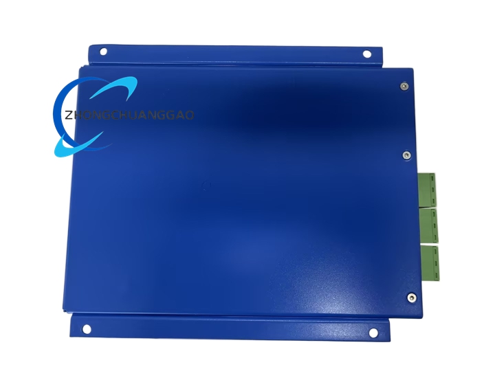
- Mounting Structure: Four-corner mounting flange holes for wall-mounted installation on electrostatic precipitator high-voltage control cabinet door
Working Principle
- Multi-channel analog signal acquisition circuit continuously collects flue gas dust concentration, temperature, pressure differential and T/R secondary high voltage/current feedback signals via isolation amplifiers to eliminate ground loop interference between field sensors and controller
- Onboard 32-bit industrial microprocessor executes proprietary hybrid AVC control algorithm; real-time calculates optimal primary voltage output target value for T/R rectifier according to dynamic flue dust load fluctuation
- Pulse width modulation firing angle control circuit outputs isolated trigger signal to T/R primary side SCR thyristor group; adjusts conduction angle to change input AC voltage amplitude of transformer rectifier unit, thereby regulating ESP high-voltage dust removal electrode voltage
- Real-time spark breakdown detection circuit monitors high-voltage secondary current mutation; once spark flashover between ESP anode and cathode plates is detected, the controller instantly cuts off SCR trigger signal for microsecond-level high-voltage shutdown, then performs gradual voltage recovery to avoid repeated spark breakdown and dust removal efficiency loss
- Built-in fault diagnosis logic continuously monitors all input/output signal channels, T/R operating parameters and internal circuit temperature; categorizes fault types (over-temperature, high-voltage overcurrent, interlock safety trip, communication disconnection) and latches fault code display on front digital screen
- RS485 Modbus communication module transmits real-time ESP operating data, spark count, fault records and control parameter values to upper computer SQControl monitoring software; also receives remote parameter modification and start/stop control commands from the monitoring system
Application Scenarios
- Thermal power plant boiler flue gas electrostatic precipitator high-voltage control core unit
- Steel mill sintering furnace, blast furnace flue dust removal ESP control system
- Cement rotary kiln industrial flue gas electrostatic dust removal equipment
- Waste incineration plant flue gas particulate capture electrostatic precipitator control cabinet
- Non-ferrous metal smelting furnace sulfur-containing flue dust removal T/R rectifier control
Installation Requirements
- Wall Mount Installation: Fix the controller enclosure vertically on ESP high-voltage control cabinet inner door with M6 stainless steel bolts; ensure front panel display window is visible to on-site operators
- Wiring Separation Standard: Strictly separate analog signal wiring, digital switch wiring and high-voltage power wiring; maintain minimum 15cm spacing between low-voltage control cables and high-voltage T/R power cables to avoid electromagnetic interference
- Terminal Wiring Torque: Spring terminal block wire clamping screws tightened to 0.7–0.9 N·m; analog signal wire adopts shielded twisted pair cable with single-end shield grounding
- Ventilation & Heat Dissipation: Maintain minimum 50mm empty space around all four sides of the controller enclosure for natural convection heat dissipation; do not install adjacent to heat-generating high-voltage T/R transformers
- Environmental Installation Restriction: Do not install outdoors without protective rain cover; avoid direct exposure to flue gas leakage sulfur-containing corrosive atmosphere
Operation & Maintenance Precautions
- Pre-Startup Inspection Rule: Before activating ESP high-voltage power supply, verify all safety interlock digital input signals (high-voltage cabinet door lockout, maintenance safety switch) are in normal closed state; any open interlock signal will trigger permanent high-voltage trip lockout
- Spark Count Monitoring Maintenance: Regularly check daily spark breakdown cumulative count displayed on front panel; if spark frequency increases sharply without flue load change, inspect ESP electrode plate fouling and insulator surface dust accumulation
- Conformal Coating Inspection: Conduct semi-annual disassembly inspection of internal circuit board conformal coating; if coating blisters or peels due to corrosive flue gas penetration, replace the controller immediately to prevent circuit short-circuit faults
- Parameter Calibration Distinction: Model 8700700-004 and 8700700-006 hardware is interchangeable, but factory pre-calibrated T/R power rating parameters cannot be mixed; re-execute full parameter calibration via SQControl software after hardware replacement
- Power Cutoff Maintenance Operation: Before opening the controller enclosure cover for internal circuit inspection, disconnect the 24VDC control power supply and wait minimum 2 minutes for internal signal sampling capacitors to fully discharge
- Long-Term Shutdown Storage: When the electrostatic precipitator system stops operation for more than 30 days, cut off the controller 24VDC power supply and seal the enclosure front panel with waterproof plastic film to prevent high-humidity flue gas residual corrosive vapor from entering internal circuits
Reviews
There are no reviews yet.