
Product Short Description
Product Overview
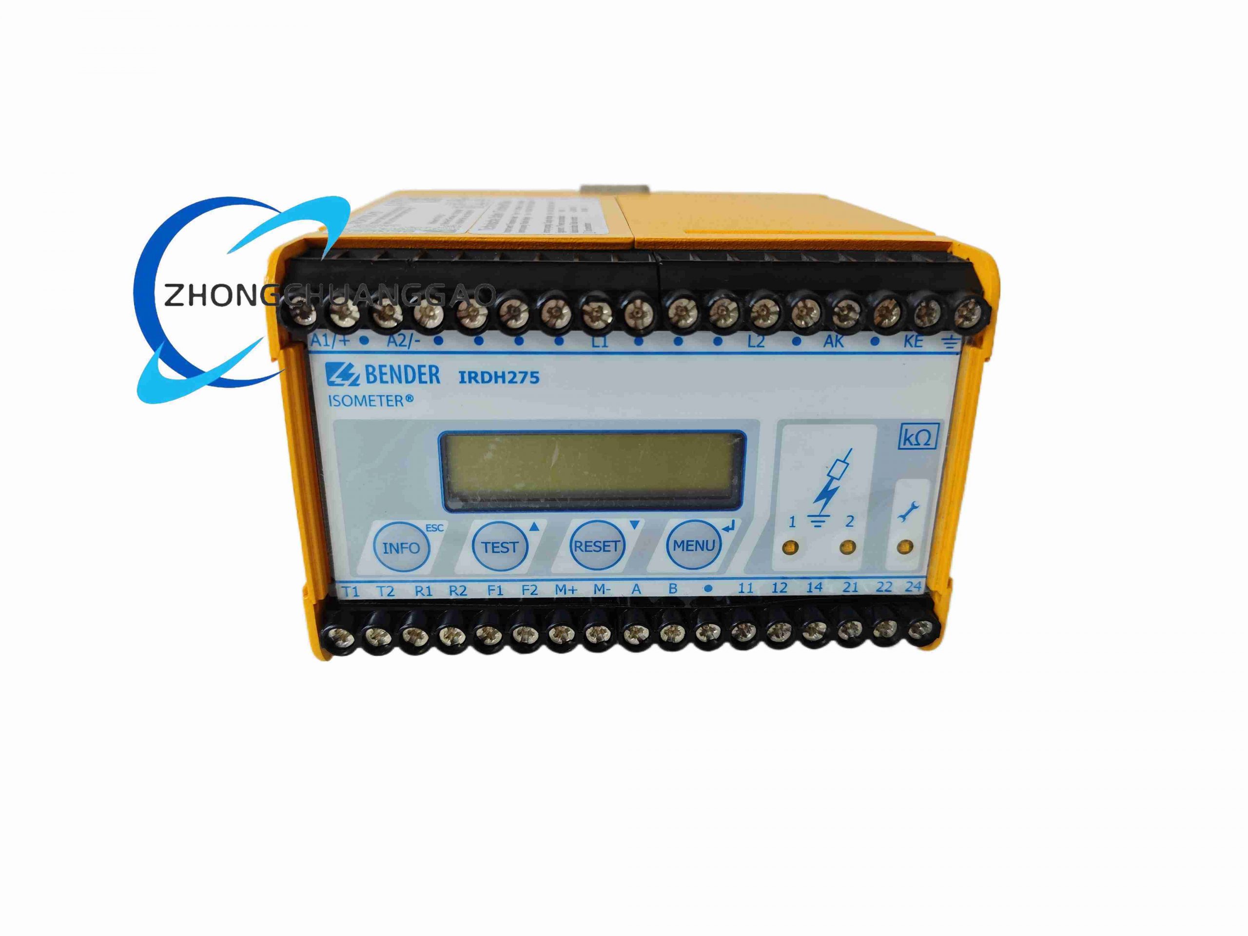
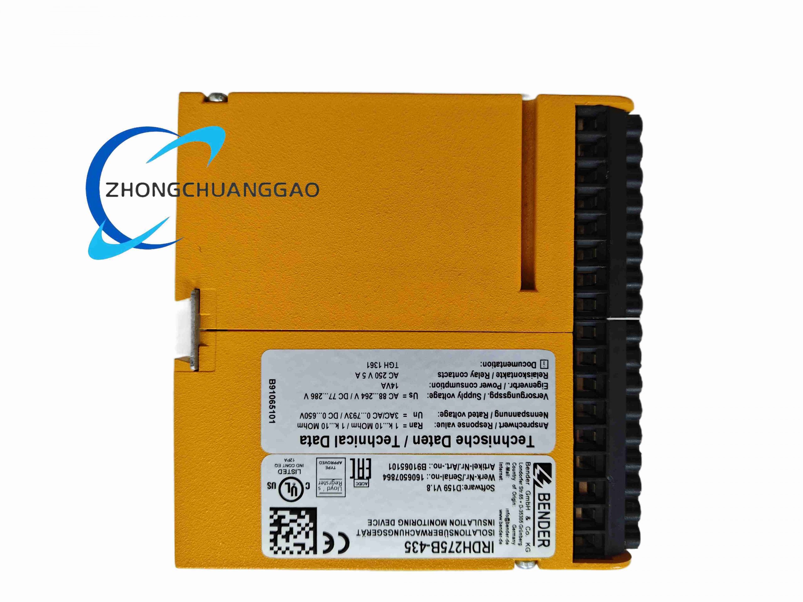
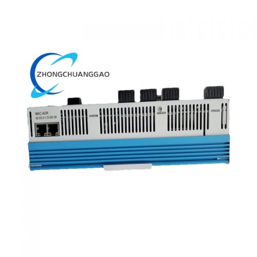
This device is professional insulation resistance monitoring equipment exclusively for unearthed AC, DC and mixed AC/DC IT power systems, adopting patented AMP Plus measurement principle to continuously track insulation resistance between live conductors and protective earth, early warning insulation aging, wire breakage and ground leakage faults, preventing electric shock hazards, equipment short-circuit damage and unplanned system shutdown in medical, industrial and new energy isolated power distribution systems.
Description
Technical Core Specifications
- Monitored System Voltage Range
- AC / Mixed AC-DC system: 0 V ~ 793 V
- Pure DC system: 0 V ~ 650 V
- Frequency adaption range: 0 Hz ~ 400 Hz (compatible with variable frequency drive output power supply)
- Insulation Resistance Threshold Parameters
- Two independent adjustable alarm response values: 1 kΩ ~ 10 MΩ continuous setting
- Measurement resolution: 0.1 kΩ real-time display on LC screen
- Power Supply Input
- Auxiliary supply voltage: AC 100 V ~ 240 V (50/60 Hz) or DC 100 V ~ 240 V dual universal supply
- Rated power consumption: ≤8 W
- Communication & Output Interfaces
- Galvanically isolated RS-485 BMS bus interface (Bender proprietary measurement communication protocol)
- 0/4–20 mA analog current output for DCS/SCADA insulation resistance retransmission
- Two independent voltage-free SPDT alarm relay contacts (10 A / 250 V AC contact capacity)
- Environmental & Mechanical Data
- Operating temperature: −20 °C ~ +60 °C
- Storage temperature: −40 °C ~ +85 °C
- Protection class: IP20 (cabinet DIN rail mount)
- Mounting: Standard 35 mm DIN rail
- Compliance standards: IEC 61557-8, DIN EN 61326-2-4, VDE 0413-8
Functional Features
- Patented AMP Plus measurement algorithm automatically adapts to system high leakage capacitance, maintaining accurate measurement under large frequency converter and rectifier load conditions
- Backlit LC liquid crystal display real-time insulation resistance value, system leakage capacitance and device parameter setting page
- Built-in real-time clock history memory, storing all insulation fault alarm records with accurate date and time stamp
- Automatic periodic self-test function for internal measurement circuit, system fault relay output when device hardware failure occurs
- External test/reset button terminal reserved for remote cabinet fault reset operation
- Relay contact logic configurable as normally open or normally closed via front panel menu
- Continuous monitoring of measuring circuit wiring breakage, automatic fault alarm when monitoring wire disconnected
Working Principle
The device injects low-amplitude measuring test signal between IT system live line and protective earth via internal isolation measuring circuit, collects return signal current to calculate real-time insulation resistance value between power circuit and ground through AMP Plus digital filtering algorithm. When measured resistance drops below pre-set alarm threshold, internal control logic drives two independent alarm relays to output switch signal; meanwhile resistance value converted to standard 4–20 mA analog signal and RS485 digital signal uploaded to upper monitoring system.
Material & Structural Composition
- Shell: Flame retardant thermoplastic integrated DIN rail enclosure with transparent front protection window
- Measuring circuit: High-precision low-drift operational amplifier, isolated signal transformer, multi-stage surge protection TVS array
- Display unit: Backlit monochrome LC liquid crystal screen with tactile membrane function buttons
- Relay components: Silver alloy contact electromagnetic safety relays with long mechanical service life
Advantage Highlights
- Unique AMP Plus technology solves measurement distortion problem of traditional IMD equipment under high leakage capacitance power systems with multiple frequency converters
- Dual independent alarm relays realize graded early warning and emergency shutdown two-stage fault signal output
- Isolated RS485 communication and analog dual output mode compatible with all mainstream industrial monitoring systems
- Universal auxiliary power supply fits global medical, industrial and new energy distribution cabinet power specifications
- Complete self-diagnosis function eliminates blind monitoring risk caused by internal device failure
Applicable Industries
Medical operating room isolated power supply, new energy electric vehicle charging station DC power distribution, marine ship IT power system, industrial frequency converter production workshop, mining underground isolated power grid, data center UPS unearthed backup power system
Installation Mandatory Requirements
- Mount vertically on 35 mm DIN rail inside closed electrical cabinet, no horizontal or inverted installation
- Measuring wire must directly connect to monitored IT system live conductor and protective earth bus, no series load equipment on measuring circuit
- Auxiliary power supply wiring must add 6 A slow blow fuse at input terminal for short-circuit protection
- Separate measuring signal wiring and high-current power wiring wiring trough to avoid measurement signal interference
Operation & Maintenance Precautions
- Execute manual self-test function every 3 months to verify complete measuring circuit integrity
- Re-calibrate insulation resistance measurement accuracy every 24 months with standard resistance calibrator
- Do not install near high-power electromagnetic contactors without metal shielding partition
- Clear LC screen dust regularly to avoid unclear resistance value reading affecting on-site judgment
Reviews
There are no reviews yet.