
Product Short Description
Product Brief Introduction
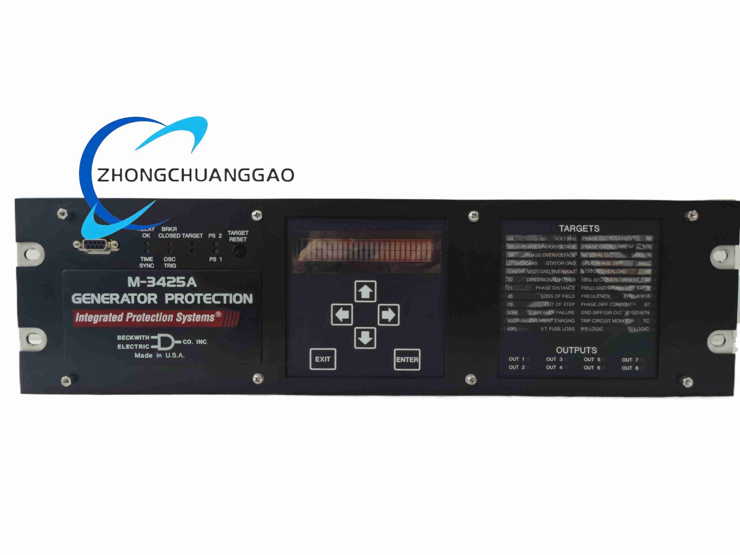
M-3425A is American Beckwith Electric flagship full-function generator protection relay, designed for comprehensive fault monitoring and rapid trip protection of synchronous generators of all capacities (hydro, gas, steam, diesel prime mover). It integrates over 30 standard generator protection algorithms, oscillographic fault recording, time-stamped event logging, dual redundant power supply and Ethernet communication, fully meeting IEEE generator protection standard requirements.
Description
Core Technical Performance Parameters
- Rated Measurement Input
- Current Transformer Input: 1 A secondary CT standard
- Voltage Transformer PT Input: 60–140 VAC 50/60 Hz
- Auxiliary Power Supply Range: 85 VDC ~ 280 VDC wide-range universal DC power
- Standard I/O Configuration
- 6 programmable binary status input channels
- 8 programmable trip/alarm output relay contacts
- Optional expansion: +8 control inputs, +15 additional output contacts
- Data Recording Function
- Oscillographic COMTRADE format fault waveform storage
- 32 groups of time-stamped fault target event records
- Protection Function Setpoints Accuracy: ≤0.5% full scale error
- Environmental Ratings
- Operating Temperature: -20 °C ~ +65 °C
- Storage Temperature: -40 °C ~ +85 °C
- Humidity: 5% – 95% RH non-condensing
Material Composition
- Main Housing: Cold-rolled steel enclosure with powder anti-corrosion coating, standard 19-inch rack mount size
- Front Operation Interface Panel: Flame-retardant ABS plastic with transparent impact-resistant polycarbonate cover
- Internal PCB: Multi-layer high-isolation FR4 circuit board with conformal anti-moisture coating
- Output Relay Base: High-temperature PA66 plastic, silver alloy contact points for arc resistance
- Rear Terminal Block: Tin-plated copper screw terminals with nylon insulating housing
Structural Characteristics
- Standard 19-inch rack-mounted single-unit enclosure, depth optimized for power system control cabinet installation
- Front panel layout: LCD parameter display, function setting buttons, multi-color fault target LED indicators, USB local debugging port
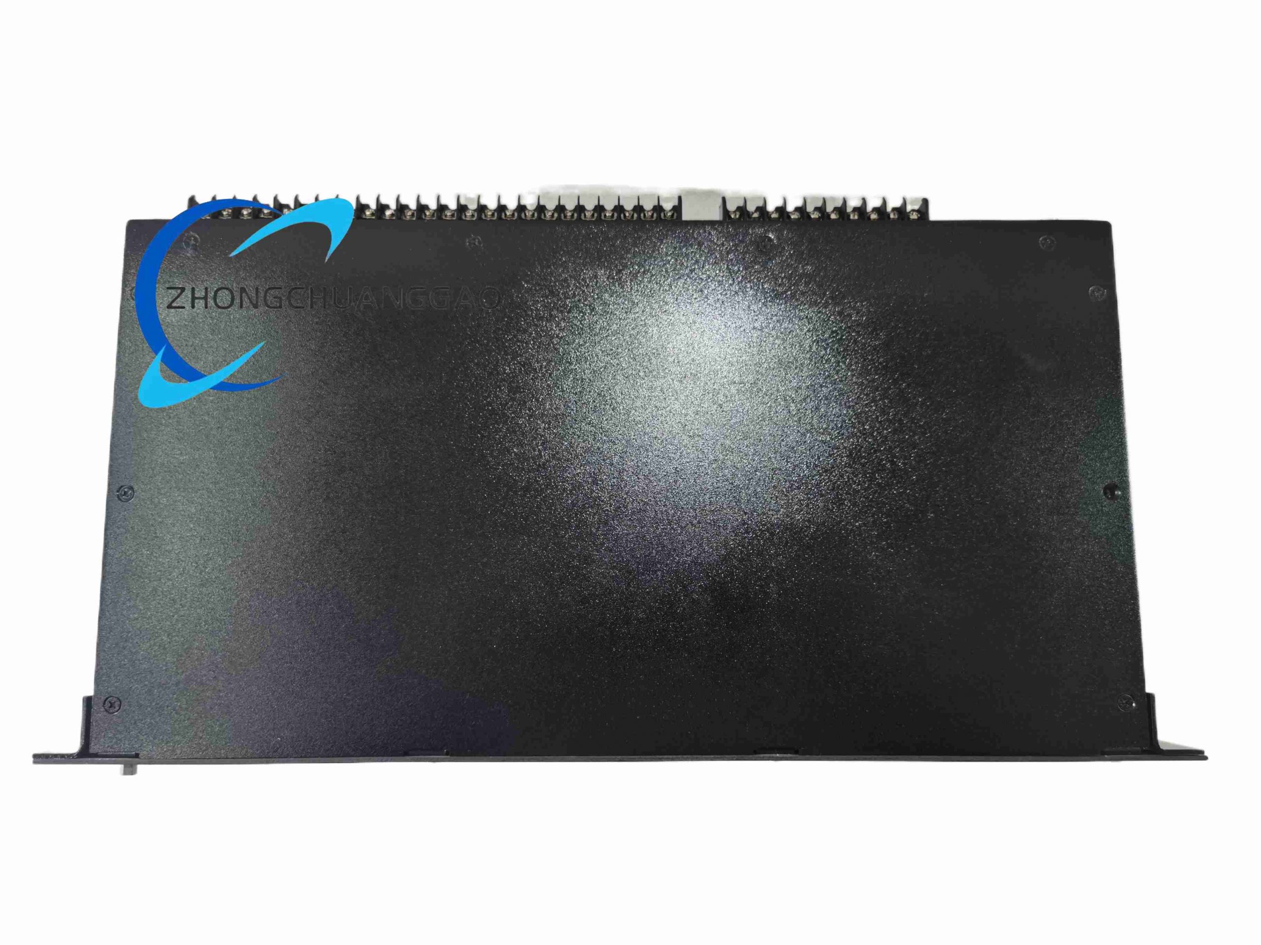
- Rear panel dense screw terminal blocks separated into CT current input, PT voltage input, auxiliary power, binary input, trip output, Ethernet communication terminals
- Internal independent isolation transformers for CT/PT signal circuits to eliminate high-voltage interference
- Optional external M-3925A target indication extension module and M-3931 standalone HMI display module interface
- Built-in hardware watchdog circuit to prevent program crash during grid voltage fluctuation
Working Principle
- Real-time sampling of generator three-phase current and voltage signals from CT/PT secondary circuits via internal isolation transformers.
- Embedded high-speed DSP chip executes all configured protection algorithm calculations simultaneously: overcurrent, undervoltage, loss of field, out-of-step, stator ground fault, reverse power, overexcitation etc.
- When electrical parameters exceed user-set protection threshold, internal logic triggers corresponding output relay contact to send trip signal to generator main circuit breaker.
- Fault waveform data and event timestamp are instantly stored to non-volatile flash memory for post-fault analysis.
- Ethernet communication port uploads real-time generator operating parameters and fault alarms to substation SCADA monitoring system via Modbus TCP / DNP3 protocol.
Installation Requirements
- Standard 19-inch cabinet rack mounting; secure four fixing screws evenly to avoid enclosure vibration loosening
- CT secondary circuit wiring strictly prohibits open-circuit operation; short-circuit CT terminals before relay wiring maintenance
- PT voltage input circuit install fuse protection at cabinet terminal strip to prevent short-circuit damage to relay internal circuits
- Separate CT/PT signal wiring from high-power trip circuit wiring, maintain 10 cm minimum wiring spacing
- Auxiliary DC power supply must install surge absorption diode at input terminal to suppress grid switching surge voltage
- Cabinet ventilation fan mandatory; continuous high-temperature operation accelerates internal relay contact aging
Function & Feature Highlights
- Complete full-range generator protection suite covering all IEEE standard required protective functions
- Base Package: Overexcitation (24), Undervoltage (27), Reverse Power (32), Loss of Field (40), Negative Sequence Overcurrent (46), Instantaneous Overcurrent (50), Breaker Failure (50BF), Overvoltage (59), VT Fuse Loss Detection (60FL), Over/Underfrequency (81), Phase Differential (87)
- Comprehensive Expansion Package: 3-zone distance backup protection (21), Out-of-Step Swing Blocking (78), 100% Stator Low-Frequency Injection Ground Fault (64S), Field Ground Protection (64F), Sync Check (25)
- Dual redundant wide-range DC auxiliary power supply improves substation power supply reliability
- COMTRADE standard oscillographic fault recording for accurate post-fault accident analysis
- IPScom dedicated configuration software supports offline parameter editing and remote relay modification via Ethernet
- Power swing blocking & load encroachment blinders prevent false tripping during grid transient fluctuation
- Multi-protocol Ethernet communication compatible with mainstream power system SCADA monitoring platforms
Typical Application Scenarios
- Utility grid-connected large steam/gas turbine generator unit protection
- Distributed industrial self-generation diesel/gas generator set control cabinet
- Hydroelectric power station small and medium water turbine generator protection
- Data center backup emergency generator safety monitoring relay
- Offshore wind farm synchronous generator fault protection system
Operation & Maintenance Precautions
- Cut off CT/PT circuit and auxiliary DC power supply before opening relay cabinet cover for parameter adjustment
- CT secondary loop always short-circuited before disconnecting relay wiring to avoid dangerous high open-circuit voltage
- Calibrate all protection threshold setpoints after every generator overhaul or CT/PT replacement
- Download fault oscillographic records after every generator trip event for failure root cause analysis
- Annual inspection of output relay contact condition; replace contacts with arc ablation marks
- Avoid installation in cabinet areas with conductive dust or condensation moisture
- Do not modify internal hardware circuit without official factory technical guidance, will void protection certification
-500x500.jpg)
Reviews
There are no reviews yet.