
Product Short Description
Product Brief
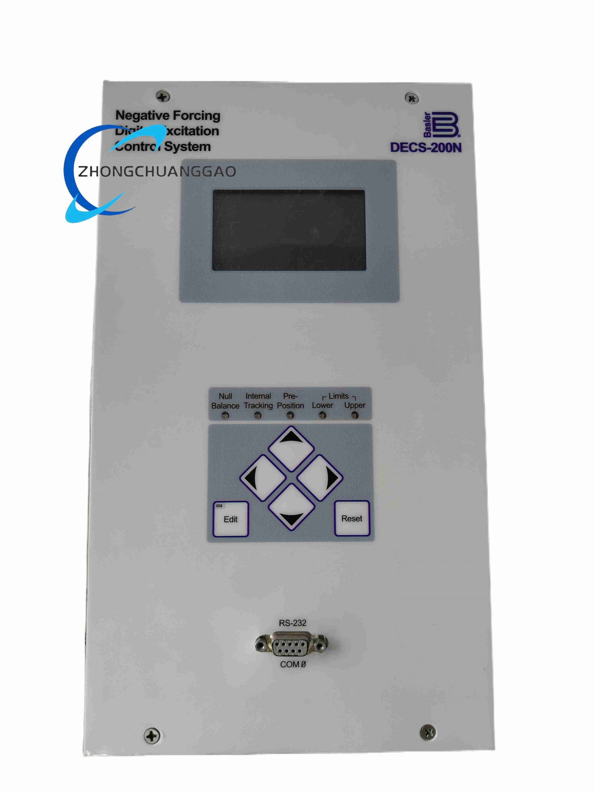
DECS-200N-C1 is single-channel negative forcing topology digital excitation regulator under DECS-200 platform, designed for synchronous generators requiring rapid demagnetization and fast voltage transient recovery. Built-in six-thyristor full-wave negative rectifier bridge realizes bidirectional excitation current output (positive boost excitation / negative demagnetization forcing), critical for power grid fault rapid voltage recovery scenarios.
Description
Model Series Definition
- DECS: Digital Excitation Control System digital excitation controller series
- 200N: Negative Forcing bidirectional excitation topology hardware platform
- C1: Single non-redundant control channel standard configuration
Technical & Performance Parameters
- Bidirectional Excitation Output Specs
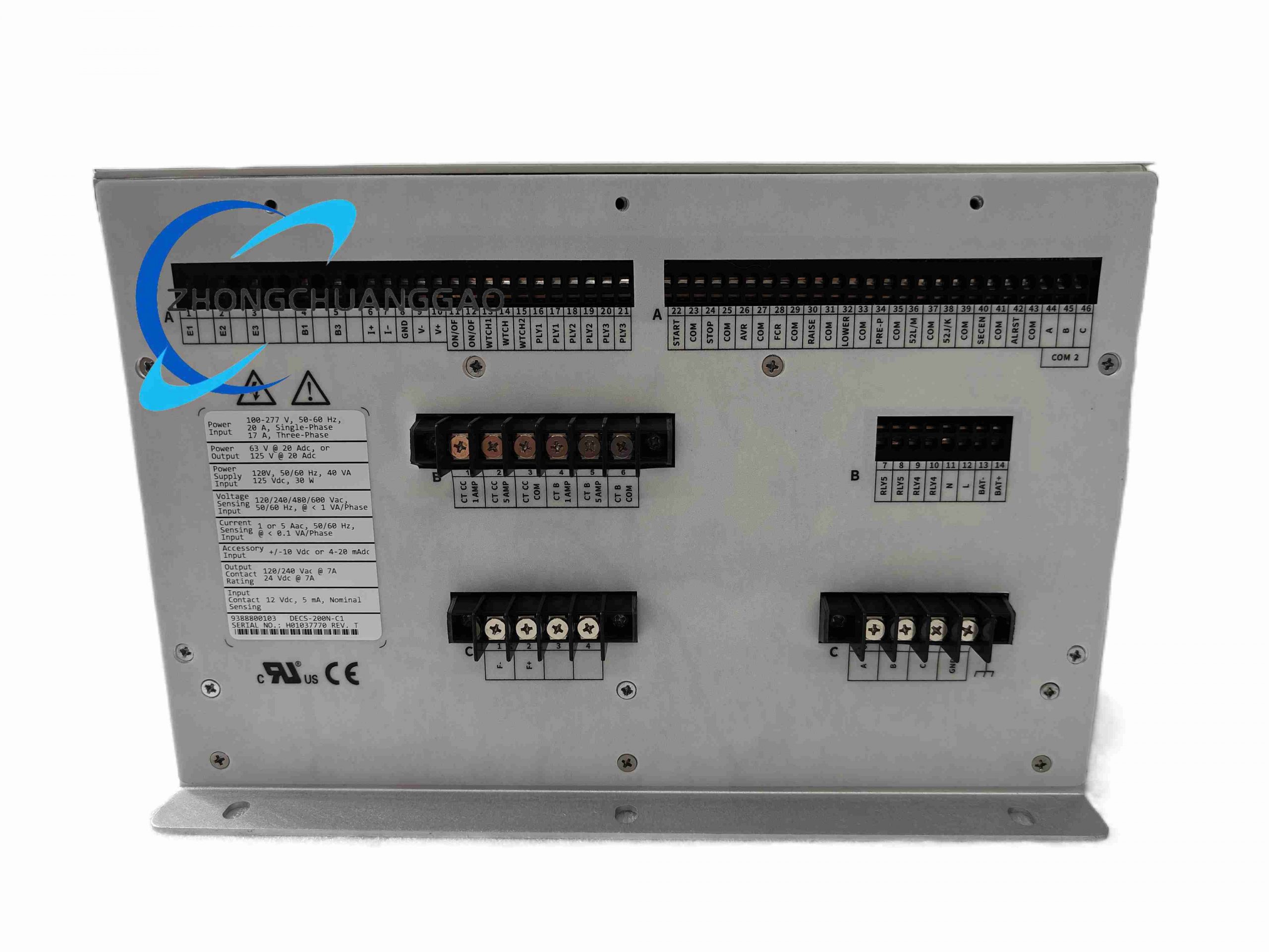
- Positive Excitation Output Voltage: 63 VDC / 125 VDC configurable
- Negative Forcing Demagnetization Output Voltage: Matches positive rated voltage range
- Continuous Positive Excitation Current: 20 ADC
- Peak Negative Forcing Demagnetization Current: 25 ADC (5-second maximum duration)
- Power Sensing & Control Input
- Voltage Sensing Range: 120–600 VAC multi-range auto-adaptive
- Auxiliary Control Power: 100–277 VAC single-phase 50–160 Hz, 50 VA rated
- Regulation & Transient Specs
- Steady-State Voltage Regulation Accuracy: ±0.25% ISO 8528-5
- Voltage Recovery Time after Grid Short-Circuit Fault: < 100 ms via negative forcing demagnetization
- Protection & Data Logging
- Full suite generator protection including negative field current over-limit protection
- 127 SER fault event records, 8 transient oscillography waveform storage
Material Composition
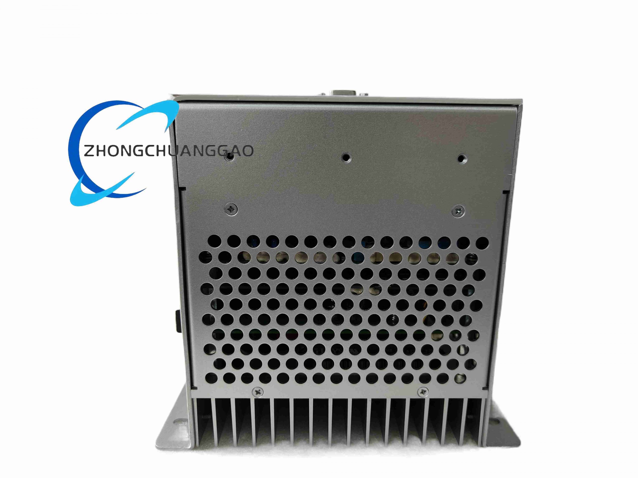
- Reinforced steel cabinet with enhanced power heat dissipation frame
- Six-thyristor bidirectional full-wave rectifier power bridge assembly for positive/negative excitation current
- Dual-side aluminum heat sinks for positive and negative power switching devices
- Anti-transient surge protection circuit integrated on sensing signal PCB
Structural Features
- Standard rack-mount housing compatible with DECS-200 series cabinet installation dimensions
- Front panel LCD display with dedicated negative forcing current real-time readout window
- Rear terminal block with independent positive/negative excitation output terminals, separate voltage sensing and auxiliary power terminals
Working Principle
Main control DSP samples generator terminal voltage and grid voltage signals; when generator terminal voltage rises above set reference value, controller triggers negative forcing thyristor bridge to output reverse DC current to rotor excitation winding, rapidly demagnetizing generator field winding to suppress overvoltage. During voltage drop events, positive excitation thyristor bridge outputs forward boost current. Bidirectional full-wave rectifier continuously adjusts magnitude and polarity of excitation current to achieve ultra-fast transient voltage regulation response speed superior to unidirectional positive forcing regulators.
Core Function Features
- Bidirectional positive boost / negative demagnetization excitation current output for ultra-fast voltage transient recovery
- Dedicated negative field current over-limit protection preventing rotor winding reverse current damage
- Native PSS power system stabilizer interface for grid-connected generator low-frequency oscillation suppression
- Local front panel and BESTCOMS™ PC software dual parameter configuration modes
- Grid parallel reactive droop compensation and U/F over-excitation protection
- Real-time negative forcing current monitoring and fault alarm output relay contacts
Advantage Highlights
- Negative forcing demagnetization topology achieves sub-100 ms generator voltage recovery after grid short-circuit faults
- 20 ADC continuous positive excitation current improves generator overload transient response capacity
- Independent negative current limiting hardware protection eliminates rotor winding reverse current thermal damage risk
- Unified mechanical dimensions with standard DECS-200 series, compatible with existing cabinet mounting brackets without structural modification
- Optimized thyristor heat sink layout extends power stage service life under frequent bidirectional current switching working conditions
Applicable Industries
Grid-connected synchronous power generators, combined cycle gas turbine power units, wind-hydro hybrid power stations, large industrial self-generation power plants, utility distributed power generation equipment requiring fast voltage dynamic responseInstallation Requirements
- Standard 19-inch single-unit rack mounting, maintain ≥120 mm rear ventilation gap for dual-side aluminum heat sinks
- Excitation output wiring must use twisted shielded high-temperature copper cables with minimum cross-section 6 mm² to withstand bidirectional peak current
- Auxiliary control power supply shall be isolated from generator main power circuit via independent isolation transformer
- Voltage sensing signal cables must be physically separated from high-current excitation output wiring with minimum 15 cm spacing
- Ambient continuous operating temperature above 50°C requires cabinet forced air cooling system with air flow rate ≥80 CFM
Operation & Maintenance Precautions
- Do not disable negative forcing current limit parameter to avoid irreversible insulation breakdown of generator rotor excitation winding
- Conduct heat sink dust cleaning every 4 months for units operating in dusty power plant environments
- Complete bidirectional excitation current calibration via BESTCOMS™ software every 24 months to guarantee regulation precision
- Avoid long-term continuous negative forcing operation exceeding 5-second rated peak demagnetization duration to prevent thyristor overheating lockout
- Inspect terminal wiring tightness every 6 months; loose excitation terminals will generate high temperature under bidirectional alternating current load
Reviews
There are no reviews yet.