
Product Short Description
Product Brief Introduction
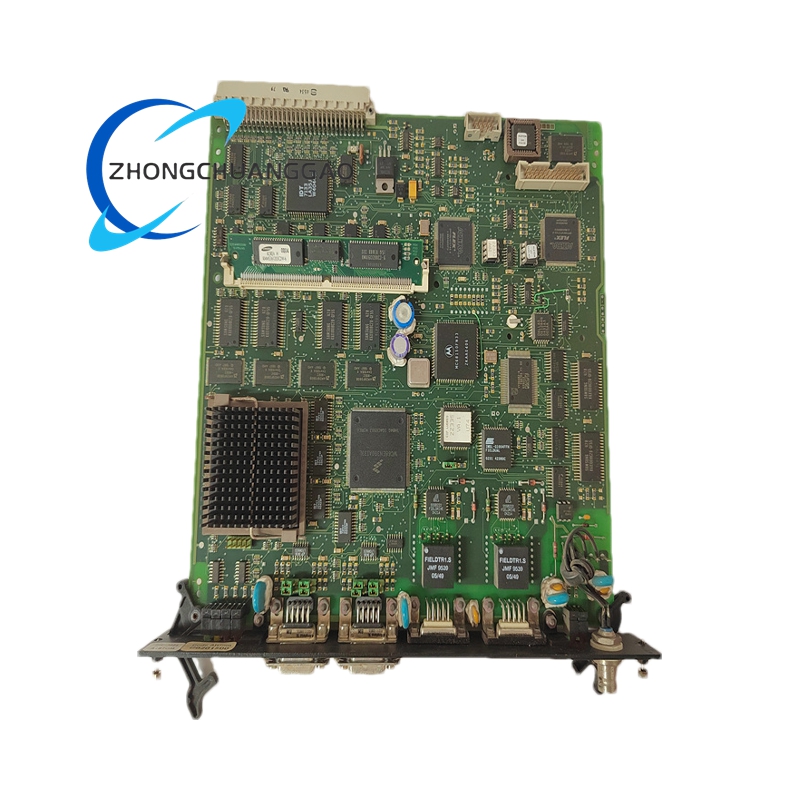
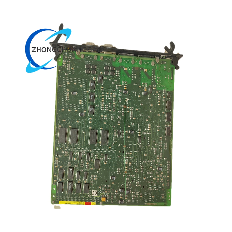
UT150-1 is a compact single-channel vibration signal conditioning transmitter developed by ALSTOM Energy division for turbine, generator and large rotating equipment protection systems. It converts raw sensor signals from eddy current displacement probes, velocity vibration sensors or piezoelectric accelerometers into standard 4–20mA analog industrial output signals compatible with PLC, DCS and alarm relay panels. The unit features integrated signal filtering, gain adjustment and fault detection circuits for continuous shaft and bearing vibration monitoring in power generation, petrochemical and heavy industrial plants.
Description
Core Technical Performance Parameters
- Input Signal Compatibility: Eddy current probe (0–24V bias), velocity sensor, piezoelectric acceleration sensor
- Standard Output Signal: Isolated 4–20mA DC analog signal, 500Ω maximum load resistance
- Frequency Response Bandwidth: 10 Hz – 10 kHz, software configurable low-pass filter cutoff
- Measurement Range: 0–200 μm displacement, 0–100 mm/s vibration velocity, 0–50 g acceleration
- Measurement Accuracy: ±0.5% full scale at 25°C reference temperature
- Power Supply Input: 24 VDC (18–32 VDC wide range industrial power)
- Isolation Level: 2500 VDC galvanic isolation between input sensor circuit and output signal circuit
- Operating Temperature: -20°C to +65°C
- Physical Size: 90mm × 60mm × 35mm DIN rail mount housing
- Weight: 0.32 kg
- Certification: ATEX Zone 2 Ex nA IIC T4, CE, IEC 61010 industrial safety standard
Function Features
- Multi-type sensor automatic signal integration; internal integration circuit converts acceleration input to velocity/displacement measurement values
- Adjustable signal gain and band-pass filtering to eliminate low-frequency structural interference and high-frequency electrical noise
- Built-in sensor cable breakage short-circuit fault diagnosis, outputs fixed 3.6mA fault current to DCS system for alarm trigger
- Galvanic isolation eliminates ground loop interference between field sensor and control room I/O modules
- DIN rail modular compact design supporting dense multi-unit cabinet layout
- Zero and span calibration adjustable via front panel potentiometers without dedicated configuration software
Working Principle
Raw vibration signals collected by field sensors are fed into the isolated input circuit of UT150-1. On-board operational amplifier circuits amplify weak sensor signals, while configurable RC filter networks remove out-of-band noise. For acceleration sensor inputs, hardware integral circuits convert acceleration waveforms to vibration velocity RMS values. A high-precision signal conversion chip translates processed vibration measurement values into proportional 4–20mA analog current output. Constant voltage bias power is supplied to eddy current probes via internal regulated circuits, with continuous impedance monitoring to detect broken sensor wiring and trigger fault current output.
Material Composition & Structural Characteristics
- Outer Housing: Flame-retardant ABS V0 grade plastic enclosure, black matte finish
- Internal PCB: FR4 anti-vibration circuit board with conformal acrylic coating for moisture and dust protection
- Terminal Connectors: Spring-type screw terminals accepting 0.5–2.5mm² copper wires
- Internal Components: Low drift precision operational amplifiers, metal film trimming resistors, solid-state tantalum capacitors
- Mounting Structure: Integrated DIN rail snap-lock plastic clip for rapid installation on standard 35mm top-hat rails
Installation Requirements
- Mount horizontally on standard 35mm DIN rail inside IP54 rated control cabinet
- Separate sensor signal cables from high-voltage power cables by minimum 30cm distance; use shielded twisted pair wiring for all sensor connections
- Shield cable grounding only at cabinet earth terminal (single-point grounding to avoid ground loops)
- Leave 10mm vertical clearance between adjacent UT150-1 modules for heat dissipation
- Calibrate zero and span parameters after wiring completion before putting equipment online
Application Scenarios
- Steam/gas turbine shaft vibration monitoring in thermal power stations
- Large generator bearing condition monitoring
- Petrochemical plant centrifugal compressor protection systems
- Hydroelectric turbine rotating component vibration detection
- Steel plant large fan and blower safety monitoring
Operation & Maintenance Precautions
- Do not install the unit in direct sunlight, areas with water splash or oil mist accumulation
- Calibration cycle recommended every 12 months; re-calibration mandatory after sensor cable replacement
- Avoid wiring sensor cables parallel to variable frequency drive power cables to prevent electromagnetic signal distortion
- Replace the unit if conformal coating shows peeling or internal water condensation after cabinet flooding incidents
- Maximum load resistance of output circuit must not exceed rated 500Ω to prevent signal saturation
Reviews
There are no reviews yet.