
Product Short Description
Product Introduction
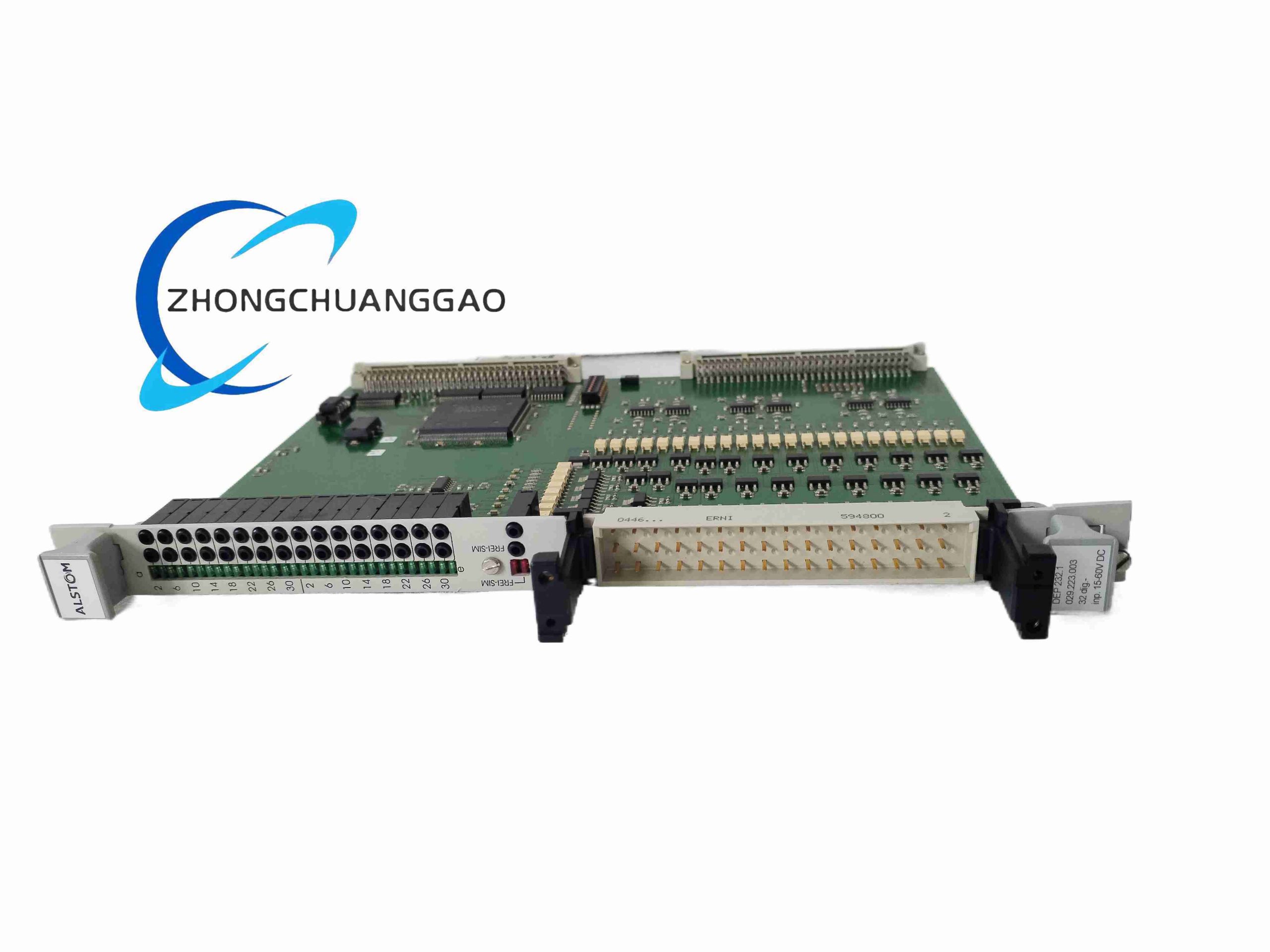
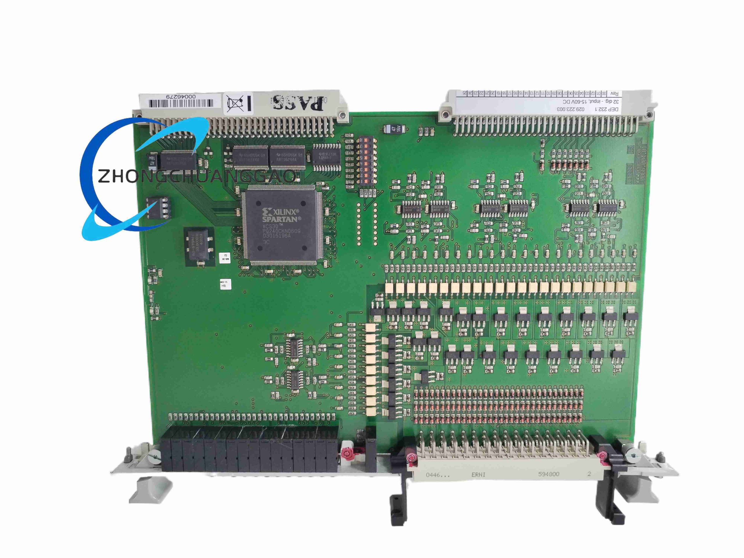
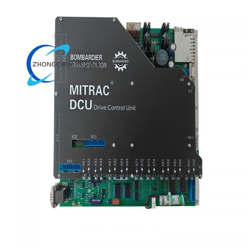
Specialized auxiliary signal processing unit matched with ALSTOM medium/high voltage power system protection relays, responsible for secondary current/voltage signal isolation, logic expansion and serial communication data forwarding in power substation protection cabinets.
Description
Technical Specifications
- Model Suffix Fixed Part Number: 029.223003 (hardware revision fixed industrial part identifier)
- Analog Signal Input: Secondary CT current 0–5 A, secondary VT voltage 0–120 VAC
- Digital Logic I/O: 16 binary input channels, 8 relay output contact channels
- Serial Communication Interface: Isolated RS232 service port, isolated RS485 station bus
- Power Supply Input: 110 VDC / 220 VDC dual-range substation control power
- Operating Temperature: -5 °C ~ +55 °C substation cabinet standard range
- Dielectric Withstand Voltage: 2 kV AC 1 minute between signal circuit and power circuit
- EMC Compliance: IEC 61000-6-2 industrial heavy electromagnetic interference standard
Functional Features
- Galvanic isolation for transformer secondary analog signals to protect main protection relay core chips
- Expand digital input/output capacity of primary protection relay equipment
- Real-time acquisition of circuit breaker auxiliary contact position signals
- Serial communication data buffer and protocol conversion for substation SCADA system connection
- On-board fault recording storage for transient overcurrent, overvoltage abnormal signal capture
- Hardware lockout logic for protection trip signal interlock control
Performance Parameters
- CT signal measurement linearity error: ≤ 0.1% rated secondary current
- Relay output contact rated capacity: 250 VAC / 5 A resistive load
- Fault record storage capacity: 512 event log entries with millisecond time stamp
- Signal processing response time: ≤ 2 ms for digital trip signal transmission
- Standby power consumption: 7.5 W, full-load operating power 14 W
Material Composition
- Cabinet module housing: Cold rolled steel sheet with epoxy anti-corrosion paint coating
- Internal PCB: FR4 high insulation substrate with tin-lead free solder coating
- Isolation components: Silicon steel core signal isolation transformers
- Output relays: Electromagnetic industrial power control silver alloy contact relays
Structural Characteristics
- Standard 19-inch rack-mounted pluggable module, 6U vertical height
- Front panel equipped with digital channel status LED indicators, service RS232 DB9 port, reset button
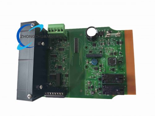
- Rear edge connector integrated all CT/VT analog wiring, power supply and bus communication terminals
- Plug-and-play hot-swap mechanical locking structure for substation maintenance without full cabinet power cut
Working Principle
High voltage substation secondary CT/VT analog signals flow through isolation transformers inside DEP232 to eliminate grid ground potential difference interference, conditioned signals are transmitted to main protection relay unit. Auxiliary circuit breaker contact digital signals are sampled by optocoupler isolation circuit, internal FPGA executes interlock and trip logic, fault events are timestamped and stored, then uploaded to SCADA system via isolated serial communication bus.
Advantage Highlights
- Standard ALSTOM protection system matching hardware with unified communication protocol compatibility
- Heavy-duty dielectric isolation prevents high voltage surge damage to core protection equipment
- Pluggable rack structure allows single module replacement without full cabinet power shutdown
- Integrated fault event logging eliminates independent fault recorder deployment cost
- Ultra-fast signal response ensures substation protection trip logic time sequence compliance
Applicable Industries
High voltage power transmission substations, medium voltage industrial distribution power rooms, hydroelectric power plants, thermal power generation stations, railway traction power supply systems
Installation Requirements
- Install module inside air-conditioned substation relay rack cabinet, maintain 5 cm vertical ventilation gap between adjacent modules
- Run CT/VT secondary wiring separately from DC control power cables with dedicated wiring duct separation
- Connect module rack ground terminal to substation protection earth grid copper strip
- Lock rear edge connector mechanical latch fully after module insertion to avoid loose signal contact
Operation Precautions
- Never open CT secondary circuit wiring while module is powered, open CT circuit generates lethal high voltage
- Disconnect all VT voltage input terminals before module disassembly maintenance
- Do not expose module to environments with conductive dust or chemical corrosive gas
- Calibrate CT signal measurement circuit every 3 years per power grid safety maintenance standard
- Do not overload relay output contacts beyond rated 5 A current capacity
Reviews
There are no reviews yet.