
Product Short Description
Product Overview
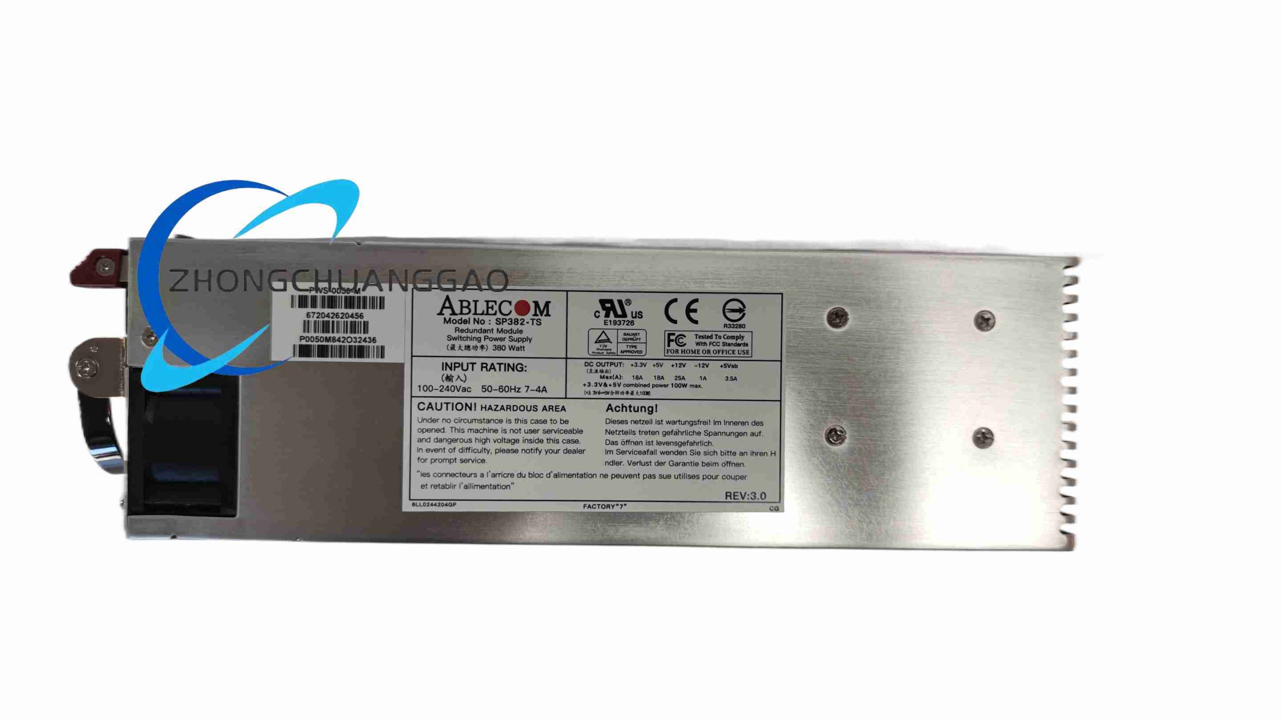
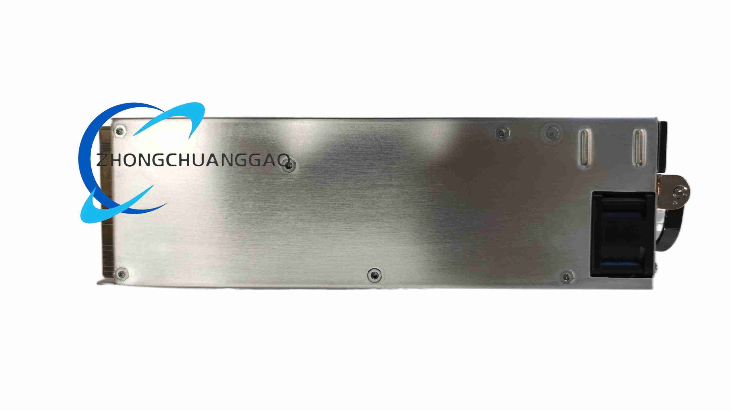
Description
Technical Specifications
- Input Electrical Parameters
- Input Voltage Range: 100VAC ~ 240VAC universal alternating current, single-phase
- Input Frequency: 47Hz ~ 63Hz wide frequency band
- Input Power Factor: ≥0.95 active power factor correction (APFC)
- Inrush Current Limit: Controlled surge current below 30A peak
- Output Electrical Parameters
- Rated Total Output Power: 380W continuous full-load
- Main Output Rail: +12VDC / 31.67A (primary power rail for server CPU, memory, storage backplane)
- Auxiliary Standby Rail: +5VSB / 3A always-on standby power for host BMC remote management chip
- Secondary Auxiliary Rail: +12Vsb / 1A auxiliary standby power
- Output Ripple Noise: ≤120mV peak-to-peak on +12V main rail
- Redundancy & Hot-Swap Core Parameters
- Parallel Redundancy Mode: Active load sharing, equal power distribution between dual modules
- Hot-Swap Support: Complete live plug-and-play without host power cut
- Fault Isolation Circuitry: Independent over-current isolation per module; single failed unit will not pull down the shared system bus voltage
- Physical & Environmental Parameters
- Module Form Factor: Standard 1U rack hot-swap power module
- Overall Dimensions: 180mm (Depth) × 90mm (Width) × 40mm (Height)
- Net Weight: 0.82kg per single module
- Operating Ambient Temperature: 0°C ~ +50°C full continuous load; derate power output by 10% when temperature exceeds 45°C
- Storage Temperature Range: -40°C ~ +70°C
- Relative Humidity: 5% ~ 90% non-condensing
- Cooling Method: Built-in high-speed PWM speed-controlled axial cooling fan
- Safety & Electromagnetic Certification
- Safety Standards: UL60950-1, IEC60950-1, CE LVD low voltage safety certification
- EMC Compliance: CE EN55032 Class B conducted & radiated electromagnetic interference standard
- Environmental Standard: RoHS lead-free hazardous substance restriction certification
- Built-In Hardware Protection Circuits
- OVP Over-Voltage Protection: Trigger shutdown when +12V rail exceeds 14.5VDC
- UVP Under-Voltage Protection: Cut output power if +12V rail drops below 10VDC
- OCP Over-Current Protection: Independent current limiting for each output rail
- OTP Over-Temperature Protection: Automatic power shutdown when internal component temperature hits 115°C
- SCP Short-Circuit Protection: Latch shutdown mode for persistent output short circuits
Functional Features
- Active APFC Power Factor Correction Circuit
Built-in high-efficiency active power factor correction topology, raising power factor above 0.95 across the full input voltage range. This feature reduces reactive power loss in data center power distribution cabinets, lowers overall facility electricity consumption, and meets strict enterprise data center power quality specifications.
- N+1 Active Load-Sharing Redundant Architecture
Two SP382-TS modules connected to the same server power backplane operate with automatic equal load distribution. During normal steady-state operation, each module carries approximately 50% of the total system load. If one unit suffers internal component failure, built-in isolation circuits instantly disconnect the faulty module from the shared power bus, and the remaining healthy unit immediately absorbs 100% of the equipment power demand with zero voltage drop or system reset.
- Full Hot-Swap Live Replacement Capability
The module’s power connector is equipped with sequential length-varied pins, implementing pre-ground contact before power signal connection during insertion, and power signal disconnection prior to ground contact during extraction. This sequential pin design eliminates electric spark arcing during live module replacement, fully protecting the server backplane and internal circuit hardware from surge damage. Maintenance personnel can swap defective modules without shutting down the host storage or server equipment.
- PWM Intelligent Variable Speed Cooling Fan
The internal axial cooling fan adopts pulse-width modulation speed regulation logic linked to internal component temperature sensors. At low operating loads and low internal temperatures, the fan runs at low rotational speed to minimize acoustic noise generation in quiet server room environments. When full load operation raises internal component temperature, the fan automatically accelerates to maximum rotational speed to deliver forced convection heat dissipation and prevent over-temperature power shutdown.
- Independent BMC 5VSB Always-On Standby Power Rail
A dedicated +5VSB 3A standby power rail maintains continuous power supply to the server’s BMC baseboard management controller chip, regardless of the main +12V power rail operating status. This persistent standby power enables remote server monitoring, power-on/power-off remote control, fault status reporting, and hardware health inspection via data center remote management networks, without requiring physical access to the server chassis.
- Real-Time Multi-Channel Hardware Fault Monitoring
Integrated internal voltage, current, and temperature monitoring circuits continuously track the operating status of all power output rails and internal power conversion components. If over-voltage, over-current, over-temperature, or short-circuit fault conditions are detected, the module immediately activates protection shutdown logic and sends a digital fault alert signal to the host BMC management chip. The server’s front panel LED status indicator will simultaneously light up a red fault warning lamp to notify on-site maintenance staff of power hardware failure.
- Built-In EMI Filter Suppression Network
Multi-stage low-pass electromagnetic interference filter circuits are integrated at the AC input port of the module. The filter network suppresses conducted electromagnetic noise generated by the internal high-frequency switching power conversion circuit, ensuring the power module complies with Class B EMC emission standards and avoids interfering with nearby sensitive network communication hardware and industrial control signal cables.
Working Principle
- AC Input Rectification & APFC Correction Stage
Single-phase alternating current from the data center power distribution cabinet enters the module through the rear AC input connector. The multi-stage EMI filter network first eliminates external power grid high-frequency interference noise. The filtered AC power then flows into a full-bridge rectifier circuit, converting alternating current into raw direct current. The active power factor correction circuit adjusts the input current waveform to synchronize with the input AC voltage waveform, eliminating reactive power loss and stabilizing the intermediate DC bus voltage to a fixed high voltage level for subsequent power conversion stages.
- High-Frequency Isolated DC-DC Switching Conversion Stage
The stabilized high intermediate DC bus voltage is fed into a high-frequency isolated forward switching converter circuit controlled by a dedicated PWM drive control chip. The PWM chip outputs variable duty cycle high-frequency pulse signals to drive power MOSFET switching tubes. High-frequency energy transfer through an isolated high-frequency transformer achieves electrical isolation between the AC input side and the low-voltage DC output side, meeting industrial safety isolation requirements. Secondary side rectifier and filter circuits convert the high-frequency transformer alternating output into stable low-voltage +12VDC main rail direct current power for the host server hardware. A separate auxiliary flyback switching converter circuit generates the constant +5VSB standby power rail for the BMC remote management chip.
- Active Load-Sharing Redundancy Control Stage
A dedicated load-sharing control integrated circuit monitors the real-time output current of each SP382-TS module connected to the shared power backplane. The control chip automatically adjusts the PWM duty cycle of each power conversion circuit to balance the output current between parallel modules, ensuring equal load distribution during normal operation. If a module suffers an internal short circuit or power conversion failure, the load-sharing control circuit triggers the internal isolation switch to disconnect the faulty module’s output circuit from the shared power bus instantly, preventing the faulty unit from dragging down the entire system DC bus voltage.
- Temperature Sensing & PWM Fan Speed Regulation Stage
Multiple negative temperature coefficient thermistor sensors are attached to the module’s high-power heat-generating components, including power MOSFET tubes, high-frequency transformers, and rectifier diodes. The thermistor sensors transmit real-time temperature analog signals to the main control chip. The main control chip adjusts the duty cycle of the fan drive PWM signal proportionally based on the detected internal temperature value, increasing fan rotational speed as internal temperature rises and reducing fan speed at low temperatures to lower operating noise.
- Multi-Layer Fault Protection & BMC Alarm Output Stage
Independent voltage sampling resistors and current sense shunt resistors continuously sample the real-time voltage and current values of all DC output rails. If sampled values exceed pre-programmed over-voltage, under-voltage, or over-current threshold limits, the main control chip immediately latches the PWM drive signal output to a disabled state, cutting off all DC power output from the module to the host hardware. Simultaneously, a digital fault notification signal is transmitted to the server BMC chip via dedicated signal pins on the power backplane connector, triggering front panel fault indicator LED illumination and remote fault log recording in the data center server management system.
Material & Structural Features
- Outer Module Housing
Stamped cold-rolled steel sheet metal enclosure with black matte electrostatic anti-rust spray coating. The front panel of the housing is equipped with a spring-loaded pull-out handle and dual-color status indicator LED lamps (green for normal operation, red for fault alarm). The rear panel integrates a standard IEC C13 AC power input socket and a metal mesh ventilation grille for cooling air exhaust.
- Internal Power Conversion Circuit Boards
Double-sided thick copper industrial printed circuit boards with high-temperature resistant solder mask coating. High-power switching components including power MOSFET tubes and rectifier diodes are mounted onto aluminum alloy passive heat sink blocks with thermally conductive silicone grease applied between component contact surfaces and heat sinks to maximize heat transfer efficiency. All small-signal control circuit areas on the PCB board are coated with transparent conformal acrylic coating to resist moisture, dust, and corrosive gas erosion in data center and industrial rack environments.
- Internal Cooling Fan Assembly
High-reliability ball bearing axial flow cooling fan fixed to the front ventilation inlet of the module housing. The fan frame is constructed from high-strength flame-retardant ABS plastic with integrated dust filter mesh to block airborne fiber dust from entering the internal circuit board space and causing heat sink blockage over long-term continuous operation.
- Hot-Swap Sequential Pin Connector
Gold-plated multi-pin hot-swap power backplane connector with variable-length sequential contact pins. Ground signal pins are manufactured with extended length to establish electrical ground connection prior to power rail contact pins during module insertion, eliminating spark generation during live hot-swap replacement operations. The connector plastic housing uses high-temperature flame-retardant plastic material complying with UL94 V-0 fire resistance rating.
- Internal EMI Suppression Components
High-performance wound ferrite core common-mode choke inductors and metal film X/Y safety capacitors integrated at the AC input stage of the PCB board, forming a multi-stage low-pass EMI filter network to suppress conducted electromagnetic interference noise generated by high-frequency switching power conversion circuits.
Installation Requirements
- Compatible Chassis Installation Standard
The SP382-TS module is designed exclusively for server/storage chassis equipped with standard 1U hot-swap redundant power backplane slots. Each chassis power slot must support N+1 parallel load-sharing power module communication and fault signal transmission. The module must be fully inserted into the backplane slot until the front panel spring locking clip clicks into place to ensure complete contact between all connector pins and the chassis power backplane.
- Dual Module Redundancy Installation Layout
For full N+1 redundant power operation, two SP382-TS modules must be installed in adjacent dedicated power slots of the host chassis. Both modules must connect to independent separate AC power distribution circuits in the data center cabinet power strip to eliminate single-point power grid failure risk; connecting both modules to the same AC power branch is prohibited for high-availability data center deployments.
- AC Power Wiring Specification
The IEC C13 AC input socket on the module rear panel must connect to the data center power distribution cabinet via certified three-core shielded server power cords rated for a minimum of 10A continuous alternating current carrying capacity. The power cord shielding layer must be single-point grounded at the data center cabinet metal ground bar to suppress external electromagnetic interference noise coupled into the AC input power line.
- Ambient Cooling & Ventilation Requirements
The server chassis front panel air intake grilles and rear power module exhaust mesh grilles must remain completely unobstructed at all times during equipment operation. A minimum clearance gap of 150mm must be reserved behind the server chassis rack to allow unimpeded hot exhaust air dissipation from the SP382-TS power modules. Installation in fully enclosed sealed rack cabinets without auxiliary rack cooling exhaust fans is prohibited; sealed cabinets without forced rack cooling will cause rapid internal temperature rise and trigger the module’s over-temperature protection shutdown function.
- Protective Grounding Specification
The metal housing of each SP382-TS module establishes protective electrical ground connection automatically through contact with the server chassis metal power backplane during full module insertion. The server rack metal frame must connect to the facility’s building safety protective ground grid via a copper ground conductor with a minimum cross-sectional wire area of 4mm² to eliminate static electricity accumulation and protect internal server hardware from electrostatic discharge damage.
Application Scenarios
- Enterprise Data Center Rack Servers
1U/2U rack-mounted file storage servers, database servers, virtualization host servers, and web application servers deployed in commercial enterprise data center facilities that demand zero unscheduled downtime and continuous 24/7 all-year-round operation.
- Network Mass Storage & Backup Hardware
EMC Data Domain series disk backup storage arrays, NAS network attached storage rack equipment, SAN storage controller chassis hardware used for enterprise business data backup, archival storage, and disaster recovery data retention systems.
- Industrial Automation Rack Control Systems
High-reliability industrial rack-mounted edge computing gateways, industrial rack server units for factory production line centralized data collection, and industrial process monitoring server hardware deployed in automated manufacturing plant control rooms.
- Telecommunications & Network Core Equipment
Rack-mounted core network switching servers, carrier-grade network traffic monitoring server chassis hardware installed in telecom operator central office equipment rooms, requiring stable redundant power supply to avoid network service outages caused by power hardware faults.
- Medical Imaging & Laboratory IT Equipment
Rack-mounted medical image storage servers, hospital laboratory data management rack server hardware deployed in hospital radiology departments and clinical testing laboratories, where uninterrupted power supply is mandatory to prevent loss of critical patient medical imaging and test data.
Operation & Maintenance Precautions
- Hot-Swap Live Replacement Operating Rules
Hot-swap module extraction and insertion operations can only be performed while the host server/storage chassis remains fully powered and operational. Before pulling the module front panel spring handle to extract the unit, confirm the front panel green power indicator LED of the faulty module has extinguished and the red fault alarm LED is illuminated, confirming internal fault isolation circuit activation. Never extract a module with the green normal operation LED lit, as this action will cause instantaneous host equipment power interruption and potential server operating system crash or data corruption.
- AC Power Supply Environmental Inspection
Conduct monthly visual inspection of all AC power cords connected to each SP382-TS module, checking for cracked cable outer insulation, frayed internal copper conductor exposure, loose IEC C13 plug connection at the module rear panel socket, or signs of heat discoloration on the plug plastic housing. Replace damaged power cords immediately to eliminate fire hazard risks from overheating electrical connections.
- Dust Filter Mesh Regular Cleaning Schedule
The dust filter mesh integrated on the module front fan inlet must be cleaned every three months during continuous 24/7 equipment operation in standard data center environments. Deployments in industrial factory control rooms with high airborne fiber dust or metal particulate contamination require filter mesh cleaning at monthly intervals. Use compressed dry air at low pressure to blow accumulated dust and fiber debris off the filter mesh surface; heavily clogged filter meshes will block cooling air intake and trigger repeated over-temperature protection shutdown faults in the power module.
- Module Fault Troubleshooting Restrictions
If a SP382-TS module repeatedly triggers red fault LED alarm conditions after hot-swap reinsertion into the chassis power slot, remove the faulty module from the chassis and replace it with a factory-new spare power module unit immediately. Do not attempt to disassemble the sealed metal housing of the faulty module for internal component inspection or repair; the internal power conversion circuit board contains high-voltage DC bus circuits that present severe electric shock hazards even after AC power input disconnection. All defective SP382-TS modules must be returned to the authorized ABLECOM service center for professional repair and component replacement; unauthorized private disassembly of the module housing voids all manufacturer product warranty coverage.
- Long-Term Spare Module Storage Requirements
Factory spare SP382-TS power modules held in inventory for equipment maintenance backup must be stored in a temperature-controlled dry warehouse storage environment with ambient temperature maintained between 10°C ~ 30°C and relative humidity controlled below 60% non-condensing. All spare modules must remain sealed inside their original factory anti-static plastic packaging bags to prevent electrostatic discharge damage to sensitive internal control circuit components. Do not store spare power modules in warehouse areas with direct sunlight exposure, high humidity condensation risk, airborne chemical corrosive gas contamination, or excessive mechanical vibration from adjacent industrial production machinery.
- Post-Maintenance Power Module Functional Verification
After completing hot-swap replacement of a faulty SP382-TS module with a spare unit, observe the front panel status indicator LED lamps continuously for a minimum 30-minute steady-state operation period. Confirm the green normal operation LED remains illuminated without intermittent flashing or red fault LED activation during the verification monitoring window. Access the host server BMC remote management software to review real-time power module voltage, current, and internal temperature telemetry data; confirm all measured electrical parameter values remain within the factory-specified normal operating range to validate successful full functional recovery of the redundant power supply system.
Reviews
There are no reviews yet.