
Product Short Description
Product Overview
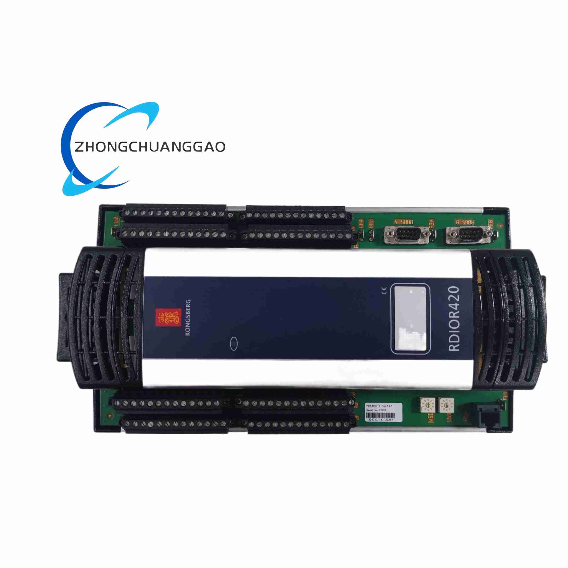
RDIOR420 is a hybrid remote I/O module designed for mixed-signal marine field control, compatible with all RCU501/502/510 master controllers via RBUS bus. The module integrates fixed split digital input and relay output channels without free channel reconfiguration, separating high-current relay output circuits and low-voltage signal input circuits with independent isolation barriers. It adopts dual redundant RBUS communication and dual power input, passes DNV, ABS, LR marine certification and SIL2 safety certification.
Description
Technical Performance Specifications
- Fixed Channel Configuration: 24 Digital Input channels + 16 Relay Output channels, non-reconfigurable channel mode
- Relay Output Load Parameters: Each mechanical dry contact relay rated load 8A @ 250VAC, 8A @ 30VDC
- Signal Isolation Design: 2000VDC galvanic isolation between input signal loop, relay output loop and RBUS communication bus
- Communication Bus Interface: Dual redundant RBUS A/B process bus, automatic bus switching within 10ms upon single channel failure
- Power Supply Standard: Dual redundant 18–32VDC marine DC power, built-in reverse polarity, surge, overvoltage and undervoltage multi-layer protection
- Channel Protection Mechanism: Every DI channel equipped with transient voltage suppression diode; every DO relay loop fitted with independent fuse and automatic short-circuit cut-off circuit
- Environmental Operating Parameters
- Operating Temperature Range: 0°C ~ +70°C
- Storage Temperature Range: -40°C ~ +85°C
- Vibration Resistance: IEC 60068-2-6 marine heavy vibration standard
- Humidity Resistance: 5%–95% non-condensing relative humidity
- Safety Certification Grade: SIL2 safety integrity level certified for marine safety interlock systems
- Physical Dimensions & Weight
- Dimensions: 200mm (H) × 100mm (W) × 120mm (D)
- Net Weight: 0.82kg
- Protection Rating: IP20, only for installation inside sealed control cabinets
Core Functional Features
- Fixed Split DI/DO Layout: 24 dedicated digital input channels for collecting limit switches, pressure switches and sensor feedback signals; 16 independent high-current relay outputs for medium-power field actuator control
- High Load Capacity Relay Contacts: 8A rated contact current, supporting direct drive of marine solenoid valves, warning sirens, small auxiliary motor contactors without intermediate relays
- Triple Independent Galvanic Isolation: Input circuit, relay output circuit and RBUS communication bus are fully isolated, eliminating electromagnetic crosstalk between strong-current output loops and weak-current signal inputs
- Dual Redundant Communication & Power Supply: Dual RBUS bus and dual DC power input design; single bus or single power supply failure cannot interrupt module operation
- Independent Overcurrent & Short-Circuit Channel Protection: Each relay output channel has dedicated current-limiting and short-circuit protection circuits; the faulty channel will be automatically cut off without affecting other normal I/O channels
- Continuous Real-Time Channel Fault Diagnosis: The module continuously monitors open circuit, short circuit and abnormal voltage state of all 40 I/O channels, and uploads precise single-channel fault codes to the RCU master controller through RBUS bus
- Configurable Communication Loss Fail-Safe Mode: When RBUS communication heartbeat signal loss exceeds 5 seconds, all 16 relay outputs automatically switch to pre-set normally open or normally closed safety state to avoid uncontrolled field equipment hazards
- Complete Power-On BIST Self-Test: Automatically inspect dual power circuits, dual RBUS bus circuits, all DI input loops and relay output drive circuits after power-on, and immediately upload all detected hardware faults to the master control unit
- Remote Online Firmware Upgrade: Supports program update via RBUS bus without module power-off, and retains all original channel fail-safe configuration parameters after upgrade
- Individual LED Status Indication: Front panel equipped with power supply status LED, RBUS A/B bus running LED, general module fault LED; each DI channel and each relay output channel has an independent small LED light to display real-time on-off status
Application Scenarios
- Marine Engine Room Auxiliary Machinery Control: Ballast water valves, fuel supply solenoid valves, bilge pump status feedback collection and relay drive control
- Ship Fire & Gas Safety Alarm System: Smoke detector, flame sensor, combustible gas detector digital signal collection, fire damper and alarm horn relay control
- Offshore Platform Deck Machinery Control: Mooring winch, anchor winch limit position feedback signal collection, deck warning light and emergency siren drive control
- Dynamic Positioning Auxiliary Monitoring System: Thruster lubrication oil pressure switch, cooling water temperature switch signal collection, auxiliary cooling valve relay control
- Inert Gas System Safety Interlock Control: Oxygen concentration feedback, pressure relief valve position signal collection, inert gas shut-off valve relay drive control
Material Composition & Structural Characteristics
- Outer Shell Material: Thickened lightweight UL94-V0 flame-retardant ABS plastic shell, vertical multi-row heat dissipation grooves on both sides to accelerate heat dissipation of high-current relay components; surface coated with anti-salt spray anti-corrosion coating suitable for long-term marine environment
- Internal Circuit Board Material: Three independent FR4 high-temperature resistant double-sided circuit boards, respectively for digital input signal processing, relay output drive and RBUS bus communication; physical isolation barriers between each circuit board to reduce signal interference; all pin terminals adopt gold-plated process to resist marine salt fog corrosion and poor contact
- Wiring Terminal Partition Design: The terminal base completely separates dual power supply terminals, RBUS bus communication terminals, 24 DI signal terminals and 16 relay output terminals, with color-coded partitions and printed clear channel serial number identification labels
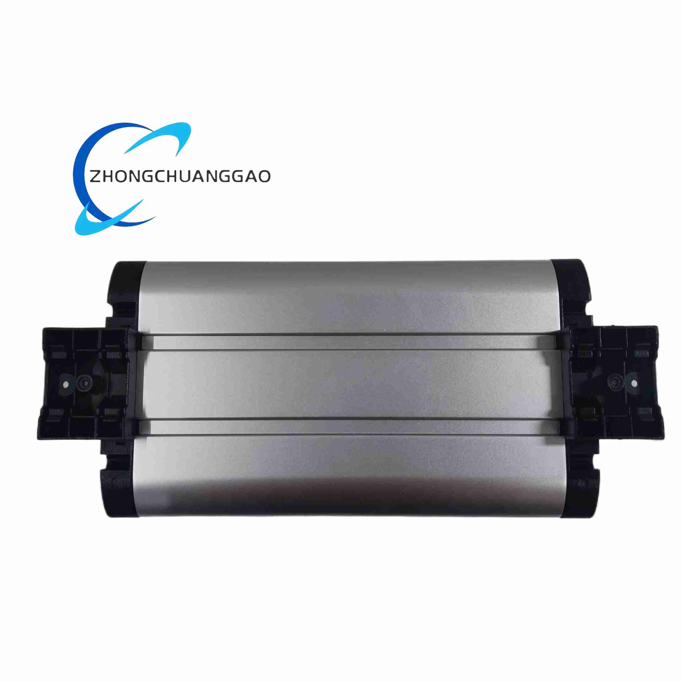
- Mounting Structure: Standard 35mm DIN rail clamping fixed structure, double-sided locking buckle design to prevent module sliding and falling under long-term ship vibration
- Front Panel LED Layout: Multi-group independent indicator lights with clear zoning; high-brightness long-life lamp beads, visible in low-light closed control cabinet environments
Working Principle
- Dual Redundant Power Conversion Stage: Two independent 24VDC power input circuits supply power to three internal circuit boards respectively; the built-in multi-stage power conversion circuit converts input DC voltage into stable 24VDC relay drive power, 5VDC signal processing power and 3.3VDC bus communication power
- RBUS Bus Data Transceiving Stage: Dual RBUS A and RBUS B bus channels receive channel control instructions and fail-safe parameter configuration data issued by the RCU master controller; upload collected DI channel switch state data and all channel fault diagnosis information to the master controller in real time
- Digital Input Signal Collection Stage: For the 24 dedicated DI channels, the internal signal processing circuit detects the on-off contact state of field sensors and limit switches, converts analog switch signals into digital signal codes, and transmits them to the bus communication circuit for uploading to the RCU master controller
- Relay Output Drive Execution Stage: For the 16 relay output channels, after receiving control commands from the master controller via RBUS bus, the internal relay drive circuit controls the pull-in or release of the built-in high-current mechanical relay contacts to switch the on-off state of medium-power field actuators connected to the relay output terminals
- Channel Fault Protection & Diagnosis Stage: Dedicated monitoring circuits continuously detect the loop state of all DI and DO channels; once a short-circuit or overcurrent fault occurs on a single relay output channel, the independent protection circuit will immediately cut off the power supply of the faulty channel, while other normal channels maintain normal operation, and the fault information is uploaded to the master controller synchronously
- Communication Loss Fail-Safe Protection Stage: The bus communication monitoring circuit continuously captures the heartbeat data packet transmitted between the module and the RCU master controller; when the heartbeat signal is lost for more than 5 seconds, the relay drive circuit automatically switches all 16 relay output contacts to the pre-configured safety state to prevent field equipment out-of-control risks
- Power-On Self-Test Execution Stage: After the power supply is connected, the module automatically runs the full BIST self-test program, sequentially inspects the dual power supply circuit, dual RBUS bus communication circuit, all 24 DI input loops and 16 relay output drive circuits; all detected hardware faults are uploaded to the RCU master controller immediately after self-test completion
Installation Requirements
- Installation Environment Restrictions: Must be installed inside a fully sealed electrical control cabinet with IP54 or higher protection grade; open-air deck installation, direct contact with seawater, salt mist and oil vapor are strictly prohibited
- DIN Rail Mounting Standard: Horizontal installation on standard 35mm top-hat DIN rail; maintain a minimum 20mm heat dissipation gap between adjacent modules on the left and right sides to ensure heat dissipation of high-current relay components inside the module
- Wiring Specification Standards
- Dual Power Supply Cable: Each power supply circuit uses an independent 1.0–2.5mm² shielded marine control cable; the two power supply terminals must be connected to two completely independent power distribution circuits to realize power redundancy
- RBUS Bus Communication Cable: Dual RBUS A/B bus wiring adopts double-layer shielded twisted-pair cable; the shielding layer of the cable is single-point grounded on the cabinet grounding busbar to eliminate strong electromagnetic interference in marine engine rooms
- I/O Signal Wiring Standard: Digital input signal wiring uses 0.75–1.5mm² shielded control cables; relay output strong-current wiring uses 1.5–2.5mm² shielded cables; strong-current power cables and weak-current signal cables adopt independent wiring grooves, with a minimum separation distance of 10cm
- Grounding Specification: The module shell grounding terminal is connected to the ship’s protective grounding busbar with a copper wire of less than 30cm in length, and the grounding resistance is controlled below 4Ω
- Pre-Power-On RBUS Node Address Configuration: Adjust the 3-bit rotary address switch on the side of the module to set the unique RBUS bus node ID; the module only reads the address value during the initial power-on startup, and the address modification requires a full module power cycle restart to take effect
Operation & Maintenance Precautions
- Power-On Operation Specifications
- Before connecting the dual power supply, verify that all wiring terminals are tightly connected and the cable insulation resistance meets the marine standard; power terminal short-circuit test is strictly prohibited
- Standard power-on sequence: First supply power to the module’s dual power supply circuits, wait for the completion of the power-on BIST self-test (all module fault LED indicators turn off), and then allow the RCU master controller to issue relay output control instructions
- Live plugging and unplugging of RBUS bus terminals and I/O signal terminals is strictly prohibited; live operation will cause bus short-circuit faults, burn internal bus communication chips and relay drive circuits, and lead to the loss of field equipment control functions
- Daily Regular Maintenance Work
- Monthly Inspection: Check the display status of all LED indicators on the front panel to confirm that there are no persistent module general faults or single-channel fault alarm lights; use a dry soft brush to clean the dust on the surface of the heat dissipation grooves on both sides of the shell, and it is forbidden to contact the module shell with liquid cleaning agents
- Quarterly Inspection: Tighten all screw wiring terminals to eliminate hidden dangers of terminal loosening caused by long-term ship navigation vibration; measure the voltage of the two groups of power supply circuits to ensure stable operation within the range of 18–32VDC; check the RBUS bus communication operating status through the monitoring interface of the RCU master controller to confirm that there are no continuous bus communication fault alarms
- Annual Maintenance: Manually trigger the full BIST self-test of the module through the RCU master controller; back up the module firmware program and all relay output channel fail-safe configuration parameters to an offline storage device for permanent data backup
- Forbidden Operations During Fault Handling
- When the module general fault LED indicator or any single-channel fault LED indicator lights up, cut off both groups of power supply circuits of the module first before disassembling and inspecting the internal circuit board; live disassembly will cause electric shock hazards and irreversible damage to internal circuit components
- Non-Kongsberg authorized professional maintenance personnel are prohibited from disassembling the module shell and replacing internal mechanical relay components and circuit board chips; all faulty RDIOR420 modules must be returned to Kongsberg’s official authorized service center for professional maintenance and full-channel function calibration
- Random modification of the communication loss relay fail-safe output state configuration parameters through the RCU master controller is prohibited; unauthorized parameter modification will lead to out-of-control hazards of marine safety interlock equipment, triggering serious navigation safety accidents
- Storage Standards for Spare Modules
- Spare RDIOR420 modules are stored in a constant temperature and humidity anti-static warehouse; the storage environment temperature range is -20°C ~ +40°C, and the relative humidity is maintained at 10%–60% without condensation
- The module must be sealed with an anti-static packaging bag during storage, and a desiccant is placed inside the packaging bag to prevent damp corrosion of the internal circuit board; it is forbidden to store the module together with corrosive chemical reagents, oil products and sea salt samples
- Spare modules stored for a long time need to be powered on to run a full BIST self-test for 1.5 hours every 6 months to prevent aging and failure of electrolytic capacitors on the internal circuit board caused by long-term power-off storage
Reviews
There are no reviews yet.