
Product Short Description
Product Overview
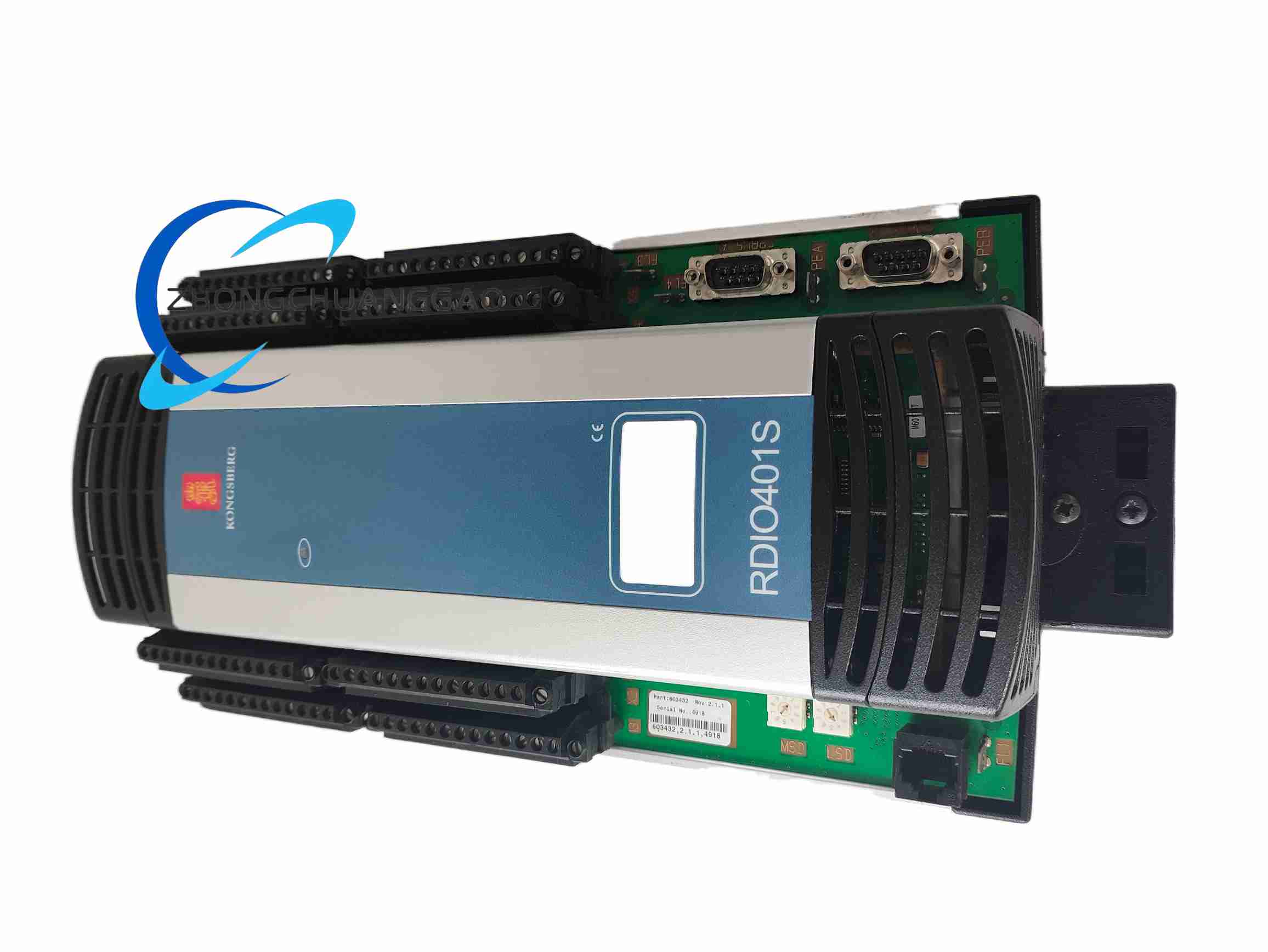
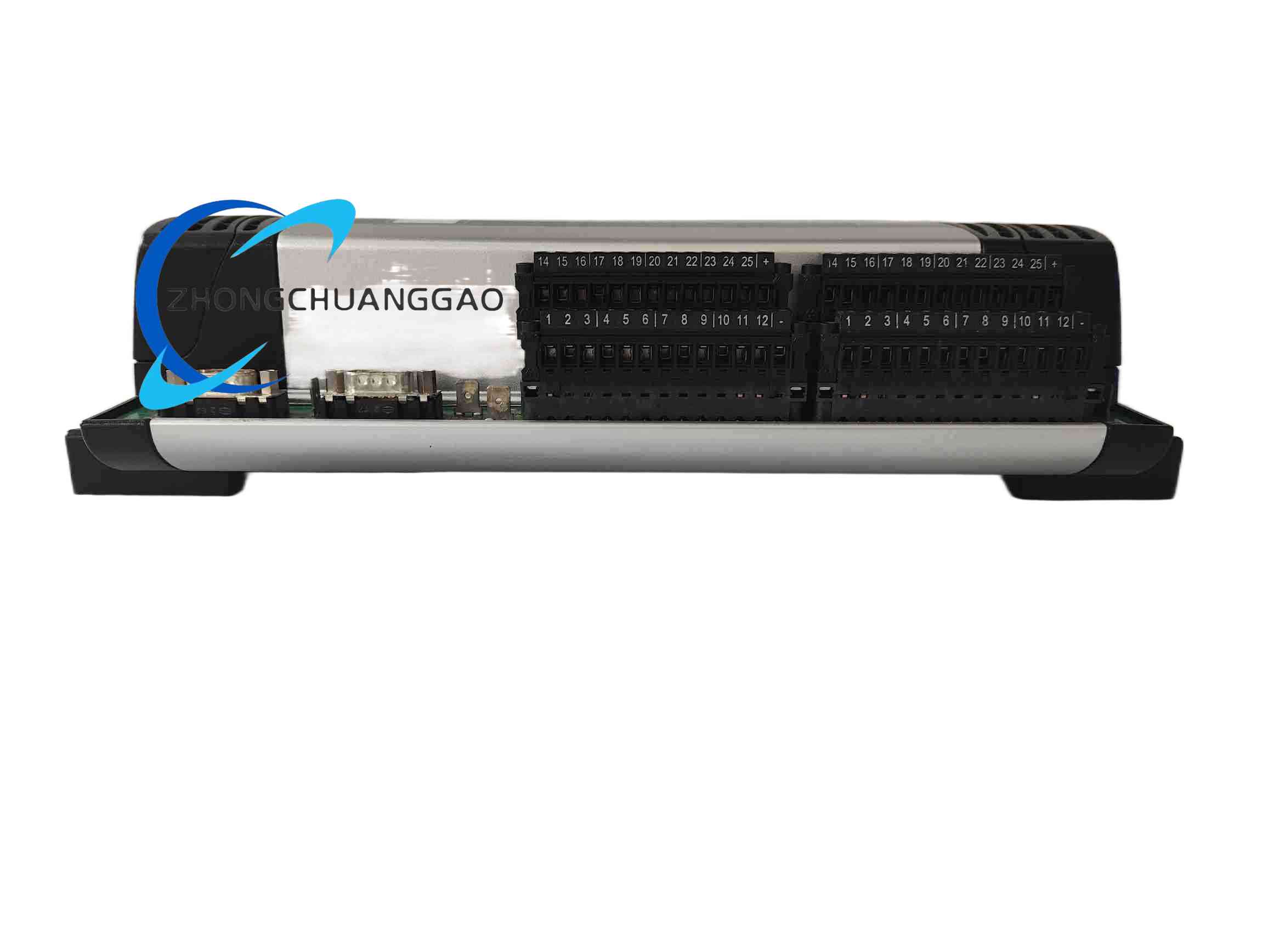
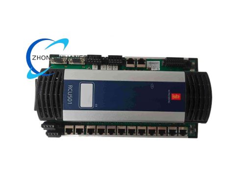
RDIO401S 603432 is a high-density remote digital I/O relay module developed by Kongsberg for marine distributed control systems, specially optimized for SIL safety system deployment scenarios, compatible with all RCU500 series master control units via RBUS remote I/O process bus. It integrates 32 configurable digital input/output channels with built-in mechanical relay output circuits, realizes decentralized collection of field switch signals and relay drive control of low-power field actuators, and reduces long-distance cable wiring quantity between field equipment and central control cabinets.
Description
Technical Performance Specifications
- Total I/O Channel Quantity: 32 independent configurable digital input or digital output channels, each channel can be independently set as DI or DO mode via master control unit configuration software
- Output Drive Type: Built-in mechanical dry contact relay for DO channels, each relay contact rated load: 5A @ 250VAC, 5A @ 30VDC
- Communication Bus Interface: Dual redundant RBUS remote I/O process bus (RBUS A + RBUS B), galvanic isolation between communication bus and internal I/O circuit, isolation voltage 1000VDC
- Power Supply Standard: Dual redundant 18–32 VDC marine DC power input terminals, built-in overvoltage, undervoltage, reverse connection and surge impact protection circuit
- Channel Protection Performance: All solid-state I/O loops equipped with independent short-circuit automatic cut-off protection circuit; built-in loop open-circuit fault monitoring function for all channels
- Operating Environmental Parameters
- Operating Temperature Range: 0°C ~ +70°C
- Storage Temperature Range: -40°C ~ +85°C
- Vibration Resistance: IEC 60068-2-6 marine standard vibration resistance
- Humidity Resistance: 5%–95% non-condensing relative humidity
- Safety Rating: SIL 2 safety integrity level certified for marine safety systems
- Physical Dimensions & Weight
- Dimensions: 180mm (H) × 90mm (W) × 110mm (D)
- Net Weight: 0.61kg
- Protection Rating: IP20 indoor electrical control cabinet installation only
Core Functional Features
- 32-channel High-density Configurable DI/DO: Each of the 32 channels can be independently configured as digital input for collecting field switch signals or digital output for driving relay contacts to control field equipment
- Dual Redundant RBUS Communication Bus: Dual independent RBUS A and RBUS B bus channels; single bus channel failure will not interrupt data communication with RCU master control unit, automatic switchover to standby bus channel
- Galvanic Isolation Between Communication Bus and I/O Circuits: 1000VDC isolation voltage eliminates electromagnetic interference crosstalk between bus communication signals and field I/O switch signals
- Dual Redundant Power Supply Anti-failure Design: Two independent 24VDC power input terminals, recommended to connect two separate power distribution circuits; single power supply circuit failure will not affect normal module operation
- Independent Channel Short-circuit Protection: Each solid-state I/O channel equipped with dedicated short-circuit protection circuit; automatic cut-off channel output current when short-circuit fault occurs, no damage to module internal circuits
- Real-time Loop Fault Monitoring: Continuously monitor open-circuit, short-circuit and abnormal signal state of all 32 I/O channels; upload accurate channel fault location codes to RCU master control unit via RBUS bus
- Communication Loss Fail-safe Output Logic: When RBUS bus communication with RCU master control unit is interrupted for more than 5 seconds, all relay output contacts automatically switch to pre-configured NO/NC fail-safe state to ensure field equipment safety
- Built-in Comprehensive Module Self-test Function: Complete hardware circuit, bus communication and all I/O channel self-inspection automatically after power-on; real-time push module fault status to master control unit
- Online Channel Configuration & Firmware Upgrade: All 32 channels DI/DO mode configuration can be modified online via RCU master control unit without module power-off; supports remote online firmware program upgrade through RBUS bus
- Status LED Fault Indication: Front panel integrated power supply status LED, RBUS A/B bus running LED, general module fault LED; each I/O channel equipped with independent channel status LED to visually display channel signal state
Application Scenarios
- Marine Engine Room Auxiliary Machinery Signal Collection & Control: Bilge pump, ballast pump, cooling water valve, fuel oil solenoid valve switch signal collection and relay drive control
- Ship Safety Alarm System Field Signal Acquisition: Fire smoke detector, temperature sensor, gas concentration detector, high liquid level float switch digital signal centralized collection
- Offshore Platform Deck Machinery Remote Control: Anchor winch, mooring winch, crane limit switch signal collection and indicator light, alarm horn relay drive control
- Marine Dynamic Positioning System Auxiliary Field I/O Monitoring: Thruster cooling system, lubricating oil system pressure switch, temperature switch signal collection
- Ship Inert Gas Safety Protection System Interlock Signal Processing: Oxygen concentration switch, pressure relief valve position feedback signal collection and interlock electromagnetic valve relay control
Material Composition & Structural Characteristics
- Outer Shell Material: Lightweight high-strength flame-retardant ABS plastic shell, two sides equipped with vertical strip heat dissipation grooves to accelerate internal relay circuit heat dissipation, UL94-V0 flame retardant grade
- Internal Circuit Board Material: Double-sided FR4 high-temperature resistant circuit board, relay drive circuits and bus communication circuits separately partitioned on circuit board to reduce signal crosstalk; all wiring pin terminals gold-plated to resist marine salt spray corrosion
- Wiring Terminal Structure: Screw-type compression terminal blocks, power supply terminals, RBUS bus communication terminals and 32-channel I/O signal terminals partitioned on terminal base, clear printed channel number identification labels
- Mounting Structure: Standard 35mm DIN rail card slot fixing, single-side locking buckle design to prevent module sliding under ship vibration
- Front Panel LED Layout: Independent LED indicators for dual power supply channels, RBUS A and RBUS B bus channels, module general fault alarm; each of the 32 I/O channels equipped with small independent status LED to display channel on/off signal state in real time
Working Principle
- Dual Redundant Power Supply Conversion Stage: Two independent 24VDC power input circuits supply power to internal circuit board; power conversion circuit converts input DC voltage into stable 24VDC relay drive power and 5VDC bus communication control power
- RBUS Bus Data Transceiving Stage: Dual RBUS A and RBUS B bus channels receive channel configuration parameters and output control instructions sent by RCU master control unit; upload collected field digital switch signal data and channel fault status information to master control unit via RBUS bus
- I/O Channel Signal Collection & Output Drive Stage
- DI Mode: When channel is configured as digital input, internal signal acquisition circuit detects on/off state of field contact switches, converts switch state into digital signal and transmits to bus communication circuit for uploading to RCU master control unit
- DO Mode: When channel is configured as digital output, after receiving control instructions from RCU master control unit via RBUS bus, internal relay drive circuit pulls in or releases built-in mechanical dry contact relay to control on/off state of field low-power actuators connected to relay contacts
- Channel Fault Monitoring & Short-circuit Protection Stage: Dedicated monitoring circuits continuously detect signal loop state of all 32 I/O channels; short-circuit protection circuit automatically cuts off channel output current when channel short-circuit fault occurs; loop open-circuit fault information is uploaded to RCU master control unit in real time
- Communication Loss Fail-safe Protection Stage: Internal bus communication monitoring circuit continuously detect data transmission heartbeat signal between module and RCU master control unit; when heartbeat signal loss exceeds 5 seconds, internal relay drive circuit automatically switches all relay output contacts to pre-configured fail-safe open/closed state to avoid field equipment out-of-control hazard
- Power-on Self-test Stage: After power supply access, module automatically executes full hardware self-test program, sequentially inspects dual power supply circuits, dual RBUS bus communication circuits and all 32 I/O channel circuits; self-test fault information is uploaded to RCU master control unit immediately after detection
Installation Requirements
- Installation Environment: Must be installed inside sealed IP54 and above electrical control cabinet; strictly prohibited open-air deck installation or direct contact with sea water, salt mist and oil vapor
- DIN Rail Mounting Standard: Standard 35mm top-hat DIN rail horizontal installation; minimum 15mm heat dissipation gap between adjacent modules on left and right sides to ensure internal relay heat dissipation
- Wiring Specification
- Dual Power Supply Cable: Each power supply terminal uses independent 1.0–2.5mm² shielded marine control cable; two power supply terminals recommended to connect two completely independent power distribution circuits to realize power redundancy
- RBUS Bus Communication Cable: Dual RBUS A/B bus wiring uses double-layer shielded twisted-pair cable; cable shielding layer single-point grounding at cabinet grounding busbar to eliminate marine electromagnetic interference
- 32-channel I/O Signal Cable: Digital input/output wiring uses 0.75–1.5mm² shielded control cable; strong current power cables and weak current I/O signal cables use independent wiring trenches, minimum separation distance 8cm
- Grounding Requirement: Module shell grounding terminal connected to cabinet protective grounding busbar with copper wire length less than 30cm, grounding resistance less than 4Ω
- Pre-power-on RBUS Node Address Configuration: Adjust the 2-bit rotary address switch on the side of the module to set unique RBUS bus node ID; module only reads address value during initial power-on startup, address modification requires module power cycle restart to take effect
Operation & Maintenance Precautions
- Power-on Operation Rules
- Verify all wiring connections are firm and cable insulation resistance meets standard before power supply access; power terminal short-circuit test is prohibited
- Power-on sequence: First supply dual power supply circuits of the module, wait for power-on self-test completion (module general fault LED off) before RCU master control unit issues channel configuration and output control instructions
- Live plugging and unplugging of RBUS bus and I/O signal terminal plugs is prohibited; live operation will cause bus short-circuit and burn internal bus communication chips and relay drive circuits
- Daily Maintenance Work
- Monthly Inspection: Check front panel LED indicator status, confirm no persistent module fault or channel fault alarm lights; use dry soft brush to clean surface dust of two-side heat dissipation grooves, prohibit liquid cleaning agent contact with module shell
- Quarterly Inspection: Tighten all screw terminal blocks to eliminate loosening risk caused by long-term ship vibration; measure voltage of two power supply circuits to ensure stable within 18–32VDC range; check RBUS bus communication status via RCU master control unit monitoring interface, confirm no continuous bus communication fault alarms
- Annual Maintenance: Manually trigger full module self-test via RCU master control unit; back up module firmware program and 32-channel DI/DO configuration parameters to offline storage device for data backup
- Fault Handling Forbidden Operations
- When module general fault LED or any channel fault LED lights up, cut off both groups of module power supply circuits first before disassembling and inspecting internal circuit boards; live disassembly will cause electric shock hazard and irreversible internal circuit damage
- Non-professional maintenance personnel are prohibited from disassembling the module shell and replacing internal relay components and circuit board chips; all faulty RDIO401S modules need to be returned to Kongsberg authorized service center for professional repair and channel function calibration
- Random modification of communication loss fail-safe output state configuration parameters via RCU master control unit is prohibited; unauthorized parameter modification will lead to field safety interlock equipment out-of-control hazard
- Spare Module Storage Standards
- Spare RDIO401S modules stored in dry constant temperature warehouse, storage environment temperature -20°C ~ +40°C, relative humidity 10%–60% non-condensing
- Modules sealed with anti-static packaging bags during storage, avoid placing together with corrosive chemical reagents and sea salt samples
- Long-term stored spare modules need to be powered on and run full self-test for 1 hour every 6 months to prevent internal circuit board capacitor aging failure caused by long-term power-off storage
Reviews
There are no reviews yet.