
Product Short Description
Product Overview
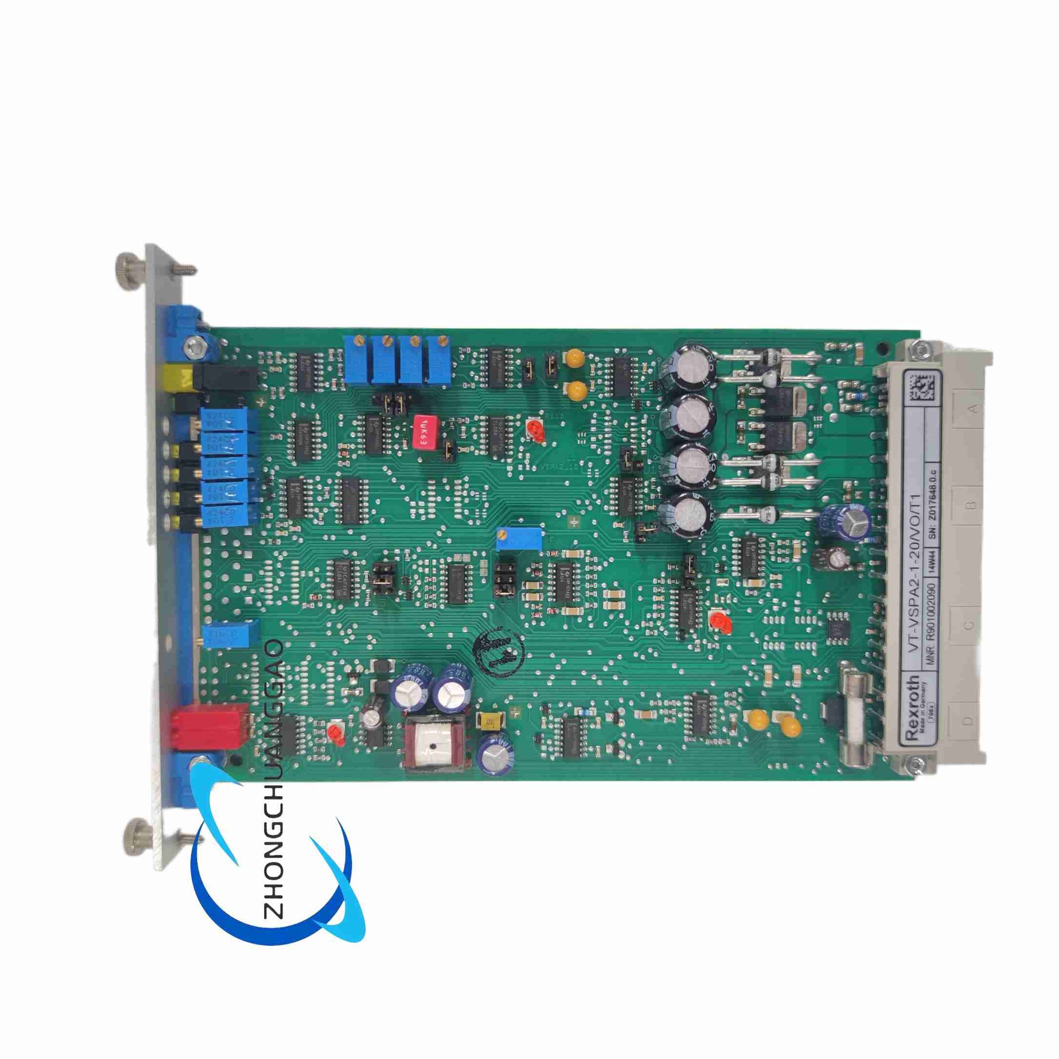
Eurocard-format analog amplifier card without valve spool position feedback loop, developed by Bosch Rexroth for 4WRA series proportional directional valves and 3DREP series proportional pressure reducing valves without built-in LVDT displacement sensors. It receives analog command signals from upper controllers and outputs proportional drive current to valve solenoids, equipped with single-section adjustable ramp function, zero and gain calibration, and complete circuit protection for open-loop hydraulic proportional control systems.
Description
Core Technical Specifications
- Material Part Number: R901002090
- Model Code: VT-VSPA2-1-20/V0/T1
- Card Standard Size: Eurocard 100mm height × 160mm depth
- Matching Card Holder: Rexroth VT3002-1-2X/48F 48-pin Eurocard rack
- Power Supply: DC 24V rated, operating voltage range 22–28VDC
- Output Drive Capacity: Continuous output current for proportional valve solenoid up to 1.2A
- Command Input Signal: Standard 0–10VDC analog voltage setpoint signal
- Ramp Function Type (T1 Version): Single fixed adjustable ramp time segment (T5 version provides 5-segment multi-stage ramp contrast)
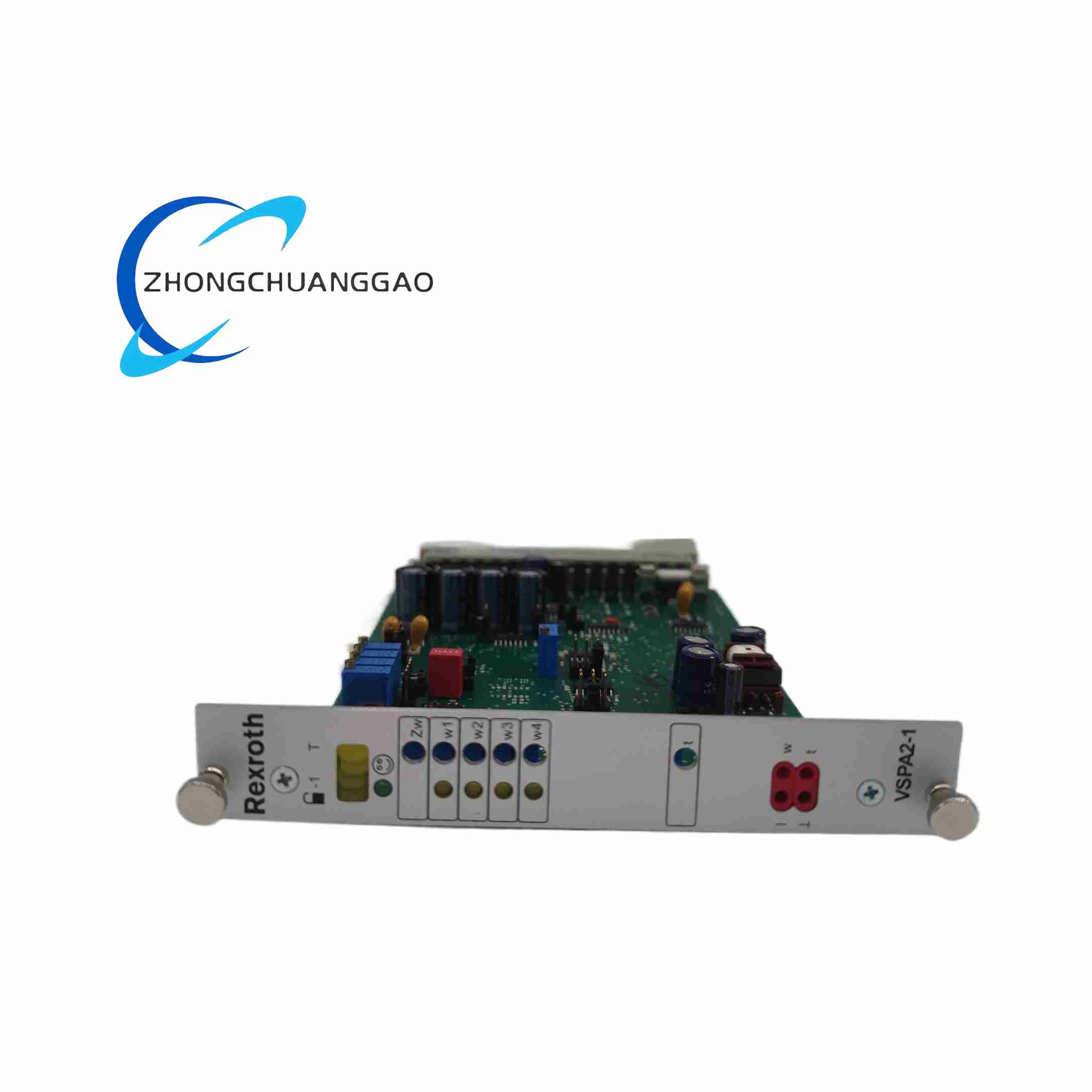
- Adjustable Front Panel Parameters: Zero offset potentiometer, output gain potentiometer, ramp time potentiometer
- Status LED Indicators: Operation enable indicator light, signal input status LED, fault overload alarm LED
- Built-In Protection Mechanisms: Reverse power polarity protection, output short-circuit current limiting, overvoltage surge protection for all input/output terminals
- Repeat Accuracy: Control output repeat precision ±0.1% FS
- Temperature Drift Coefficient: ≤ -0.1% per 10°C ambient temperature change
- Operating Frequency Adaptation: 300–410Hz internal oscillation frequency, compatible with 4WRA6 and 4WRA10 proportional directional valves
- Net Weight: 0.6kg
Function Features
- Open-Loop Proportional Drive Control: Designed for proportional valves without spool position feedback sensors; outputs drive current linearly proportional to the input command voltage signal
- Single-Stage Adjustable Ramp Soft Transition: Convert step input command signal into smooth gradient output current, reduce hydraulic flow sudden change impact, avoid machine tool feed jump, injection molding pressure impact
- On-Site Zero & Gain Calibration Potentiometers: Front panel exposed adjustable knobs for field calibration of valve zero drift and full stroke output gain without modifying PLC control program
- Multi-Type Command Signal Compatibility: Support single-ended 0–10V voltage signal, external 4–20mA current command signal via external conversion resistor
- Full Visual Fault Diagnostic LEDs: Independent LED indicators to display power-on enable state, command signal presence, output overload/short-circuit fault status for rapid equipment troubleshooting
- Universal Compatibility with Rexroth Proportional Valves: Perfect matching 4WRA6-2X, 4WRA10-2X proportional directional valves, 3DREP6-2X proportional pressure reducing valves; can directly replace old generation VT-VSPA series amplifier cards for system upgrade
- Complete Hardware Safety Protection Suite: Reverse power connection will not damage internal circuits; solenoid coil short-circuit automatically limits output current, alarm LED lights up to remind maintenance personnel of fault location
Application Scenarios
- Small and medium CNC machine tool proportional feed hydraulic valves open-loop drive
- Injection molding machine proportional pressure, flow control hydraulic loops
- Light industry packaging machinery, textile machinery hydraulic proportional adjustment
- Hydraulic clamping equipment, small hydraulic press proportional pressure regulation
- Hydraulic auxiliary systems of automated assembly production lines
Material & Structural Characteristics
- PCB Circuit Board: Multi-layer industrial FR4 high-temperature resistant circuit board, independent analog signal ground layer and power ground layer to isolate electromagnetic interference
- Front Panel Assembly: Thick black plastic panel with complete silk-screen parameter labels, metal rotary potentiometers with locking function to prevent vibration parameter drift
- Back Connector Interface: Standard 48-pin Eurocard gold-plated connector, high wear resistance for repeated disassembly and maintenance
- Internal Electronic Components: High-precision metal film potentiometers, low-temperature drift operational amplifiers, anti-interference optocoupler chips for digital enable signals, high ripple resistance electrolytic capacitors
- Card Installation Structure: Horizontal insertion into standard Eurocard rack, front panel with metal lock buckle to fix the card and avoid loose contact caused by equipment vibration
Working Principle
- Command Signal Filtering: The upper PLC outputs 0–10V analog setpoint voltage, enters the amplifier’s input circuit, and eliminates high-frequency electromagnetic interference noise through RC low-pass filter circuit
- Ramp Time Conversion Circuit: The filtered step command signal passes through an adjustable RC ramp circuit controlled by the front panel potentiometer; the circuit slows down the signal change rate to generate smooth linear gradient control signal
- Gain & Zero Offset Adjustment Circuit: The ramp signal enters the adjustable gain potentiometer to set full-scale output amplitude, then passes through the zero offset potentiometer to compensate the valve inherent zero drift error
- Power Drive Output Stage: The adjusted weak analog control signal drives the power transistor output stage, converting low-power control signal into high-current drive output to actuate the proportional valve solenoid coil; the output current changes linearly with the input command voltage
- Protection & Indication Logic: When DC 24V enable signal is connected, the enable LED lights up and the output stage is activated; if the solenoid coil is short-circuited or overloaded, the internal current limiting protection is triggered, the fault alarm LED turns on, and the drive output is temporarily cut off to protect the amplifier and valve coil
Installation Requirements
- Card Rack Matching Installation: Insert the amplifier card fully into the Rexroth VT3002-1-2X/48F 48-pin Eurocard rack, lock the front panel metal buckle to ensure the back 48-pin connector fully contacts the rack socket without gap
- Cabinet Environment Installation Standard: Install only inside sealed industrial electrical control cabinets with oil mist, dust isolation; cabinet internal operating temperature must be controlled between 0°C and +60°C
- Wiring Specifications:
- DC 24V power cable: 0.75–1.0mm² shielded wire, separate wiring channel from analog signal cables
- Analog command signal wire: 0.5mm² double-shielded twisted pair cable, single end grounding at the card rack equipotential ground bus
- Proportional valve solenoid drive cable: 1.0mm² shielded wire, separate routing from contactor, relay digital signal lines
- Equipotential Grounding Requirement: Connect the metal card rack frame to the cabinet main grounding bus with a 1.5mm² copper ground wire to eliminate electromagnetic interference causing analog signal drift
- Electromagnetic Isolation Spacing: Maintain at least 12cm distance between this amplifier card and high-power inverters, servo power drive modules, AC contactors inside the cabinet to avoid strong electromagnetic interference affecting control precision
Operation & Maintenance Notes
- All zero point and gain potentiometer calibration must be completed under the hydraulic system’s normal working pressure; adjust the potentiometer in small rotation increments, avoid over-adjustment leading to valve spool overtravel
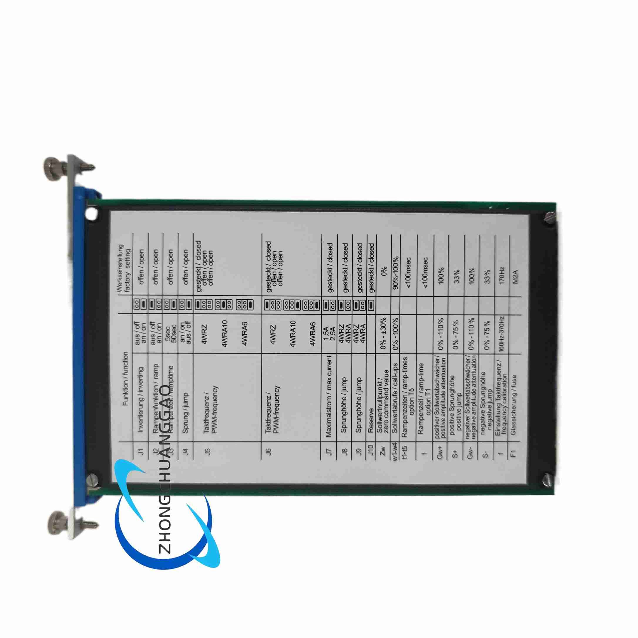
- Adjustment of internal ramp time jumpers must be carried out after cutting off the entire card rack DC 24V power supply; live adjustment will cause sudden valve action and risk equipment collision damage
- Every 3 months, pull out the amplifier card and use anhydrous alcohol cotton swabs to clean dust and oil film accumulated on the back 48-pin gold-plated connector; dirty contacts will cause signal interruption and unstable hydraulic proportional action
- Do not input AC voltage into the DC 24V power terminal; AC power surge will permanently damage the internal power supply circuit of the amplifier card
- After the proportional valve coil short-circuit fault is eliminated, cut off and re-supply the DC 24V power supply to reset the amplifier’s overload protection state; the fault alarm LED will extinguish after reset
- Do not disassemble the amplifier front panel and internal circuit board without professional hydraulic electrical maintenance personnel; disassembly will damage precision potentiometers and analog signal processing circuits, invalidating the original factory warranty
Reviews
There are no reviews yet.