
Product Short Description
Official Full Product Name
4-Slot Universal AC PXI Chassis (Discontinued End-of-Life Hardware)
Product Brief Introduction
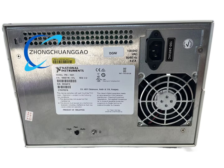
Compact desktop/portable PXI backplane chassis compliant with PXI Hardware Specification Rev 2.2, designed for low-noise laboratory, office and educational test systems. Equipped with a 400W universal AC power supply, temperature-controlled variable fan, and full PXI synchronization bus architecture to support all standard 3U PXI and CompactPCI peripheral modules
Description
Core Technical & Performance Specifications
- Slot Layout: Total 4 slots, 1 dedicated PXI system controller slot + 3 peripheral signal I/O slots
- Backplane Clock & Trigger: Onboard low-jitter 10 MHz system reference clock; full PXI star trigger bus, local bus, trigger routing bus
- Electrical Power Input:
- AC Input Voltage: 100–240 VAC universal range, operating tolerance 90–264 VAC
- Input Frequency: 50/60 Hz nominal, operable band 47–63 Hz
- Rated Input Current: 2A–4A
- Power Supply Efficiency: ≥70% under full rated load
- DC Backplane Rails: +3.3 V, +5 V, ±12 V; line regulation ≤±0.2% for 3.3 V, ≤±0.1% for 5 V/±12 V
- Cooling & Acoustic Noise: AUTO/HIGH two-speed fan control; minimum acoustic noise 35 dBA at AUTO low-speed mode (ISO 7779 standard measurement)
- Environmental Operating Range: 0 °C to 55 °C ambient temperature; 10%–90% non-condensing relative humidity; maximum operating altitude 2000 m
- Physical Dimensions & Weight: Width 257.1 mm, Height 177 mm, Depth 340 mm; total unit weight 5 kg
Key Functional Features
- Dual fan speed control: AUTO mode dynamically adjusts fan speed based on intake air temperature to minimize audible noise; HIGH mode locks full fan speed for high-power module full-load operation
- Front-panel momentary standby power switch for convenient system power cycling without AC cable disconnection
- Full compatibility with all 3U PXI Rev2.2 and CompactPCI PICMG 2.0 R3.0 modules
- Integrated complete PXI synchronization infrastructure: 10 MHz shared clock, star trigger, local inter-slot communication bus
- Optional mechanical accessories: Portable carrying handle kit, rack-mount bracket kit for standard 19-inch industrial equipment cabinets, rubber anti-slip bottom feet
- Full short-circuit, overload, overvoltage protection for all backplane DC power rails
- System configuration fully supported by NI MAX (Measurement & Automation Explorer) software, automatic generation of pxisys.ini system definition file for hardware identification and resource allocation
Working Principle
- AC mains power enters the integrated internal switching power supply unit, converts universal AC input to stabilized multi-channel DC power rails for the PXI backplane circuit board
- The backplane PCB distributes DC power, PCI bus data lines, 10 MHz reference clock signals, and multi-layer trigger bus signals to every installed peripheral module slot
- Built-in temperature sensor continuously samples chassis intake air temperature to control fan speed logic circuit, automatically increasing fan rotation speed when internal temperature rises above predefined threshold
- The front-panel power switch acts as secondary control logic to cut DC power output to the backplane without disconnecting the main AC input cable
- The 10 MHz low-jitter clock oscillator distributes synchronous timing reference to all slots to enable multi-module time-aligned synchronized measurement and control operations
Structure & Material Composition
- Outer Enclosure Main Body: Sheet aluminum formed frame + cold-rolled steel side panels
- Surface Finishing: Aluminum components treated with clear chromate conversion coating; steel panels electrodeposited nickel plating + polyester urethane powder paint for corrosion resistance
- Backplane Bare Circuit Board: UL 94 V-0 flame retardant FR4 PCB material
- Backplane Slot Connectors: IEC 917 & IEC 1076-4-101 compliant gold-plated connectors, UL94 V-0 rated plastic housing
- Internal Cooling Fan: Plastic fan housing, aluminum fan blades, brushless DC motor
- Hardware Fasteners & Internal Brackets: Extruded aluminum support frames, nylon plastic filler panels for empty slots
Installation Mandatory Requirements
- Mechanical Installation Rules
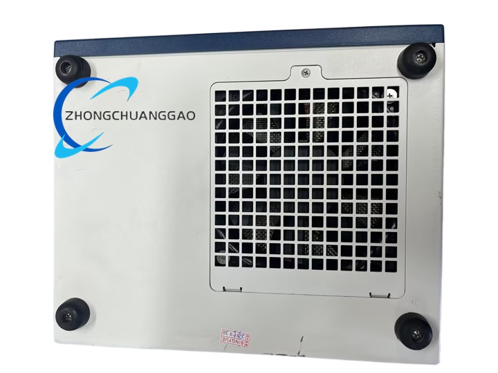
- Desktop placement: Install all four rubber anti-slip feet to chassis bottom surface to ensure stable placement and bottom airflow clearance
- 19-inch rack mounting: Must use official NI rack-mount accessory kit; install filler panels on all empty unused slots to maintain uniform forced-air cooling airflow
- Portable mobile use: Mount optional carrying handle kit on chassis side panels; avoid tilting chassis more than 15 degrees during operation
- Electrical Installation Rules
- Connect chassis to reliable protective earth ground via rear-panel chassis ground screw to eliminate ESD and EMI interference
- Only use factory-provided matched AC power cable compatible with local mains socket standards (NEMA 5-15, SEV, AS C112 regional variants)
- Install modules only when chassis main AC power is fully disconnected; insert modules fully into backplane slot connectors and fasten front-panel retention screws tightly
- Software Installation Rules
- Install NI DAQmx base driver suite and NI MAX configuration software on host control PC before powering on the chassis
- Complete hardware self-test and resource mapping inside NI MAX after first power-up
Strict Usage Precautions
- Thermal & Cooling Precautions
- Never block front intake air vents or rear exhaust vents; maintain minimum 100 mm clearance at chassis rear for hot air exhaust
- Always install plastic filler panels on every empty slot; missing filler panels disrupt internal airflow, causing module overheating and shortened hardware service life
- When operating multiple high-power modules simultaneously, manually switch fan to HIGH speed mode to prevent thermal throttling
- Electrical Safety Precautions
- Disconnect main AC power cable before inserting, removing, or reconfiguring any PXI peripheral modules to avoid backplane short-circuit damage
- Do not connect AC mains power with damaged, frayed, or improperly terminated power cables; damaged cables create electric shock and fire hazards
- Avoid operating the chassis in environments with conductive dust, liquid splashes, or high humidity exceeding 90% non-condensing rating
- Mechanical & Storage Precautions
- Handle chassis with care; avoid dropping or heavy impact, which can crack the backplane PCB or damage gold-plated slot connectors
- When storing chassis long-term, remove all installed modules, place chassis in dry, temperature-controlled storage space with humidity between 20%–60%
- Clean chassis exterior only with dry soft microfiber cloth; never use liquid cleaning solvents or compressed air to blow internal backplane circuits
- ESD Protection Precautions
- Always wear certified ESD grounding wrist strap when handling internal modules or chassis backplane components
- Touch chassis rear-panel ground screw to dissipate static charge before touching any exposed circuit board or connector pins
Target Application Scenarios
- Educational laboratory teaching platforms for university electrical engineering, automation, and test measurement courses
- Low-noise desktop small-scale automated functional test systems for consumer electronics PCBA validation
- Portable field measurement test equipment for low-channel-count sensor data acquisition
- Small industrial bench process control systems with limited I/O channel requirements
- Research laboratory low-power signal characterization and sensor calibration test benches
Reviews
There are no reviews yet.