
Product Short Description
Product Introduction
This is a dedicated rack pluggable power supply module designed exclusively for Yokogawa STARDOM FCN series field control stations. It accepts 24V DC industrial standard input power and converts it into stable +5.1V DC system logic power and isolated 24V DC field bus power for CPU modules, I/O modules and FOUNDATION Fieldbus communication circuits on the system baseplate. It supports duplex redundant parallel power supply configuration and full hot-swap replacement under live operating conditions without interrupting control system power supply.
Description
Core Technical Specifications & Performance Parameters
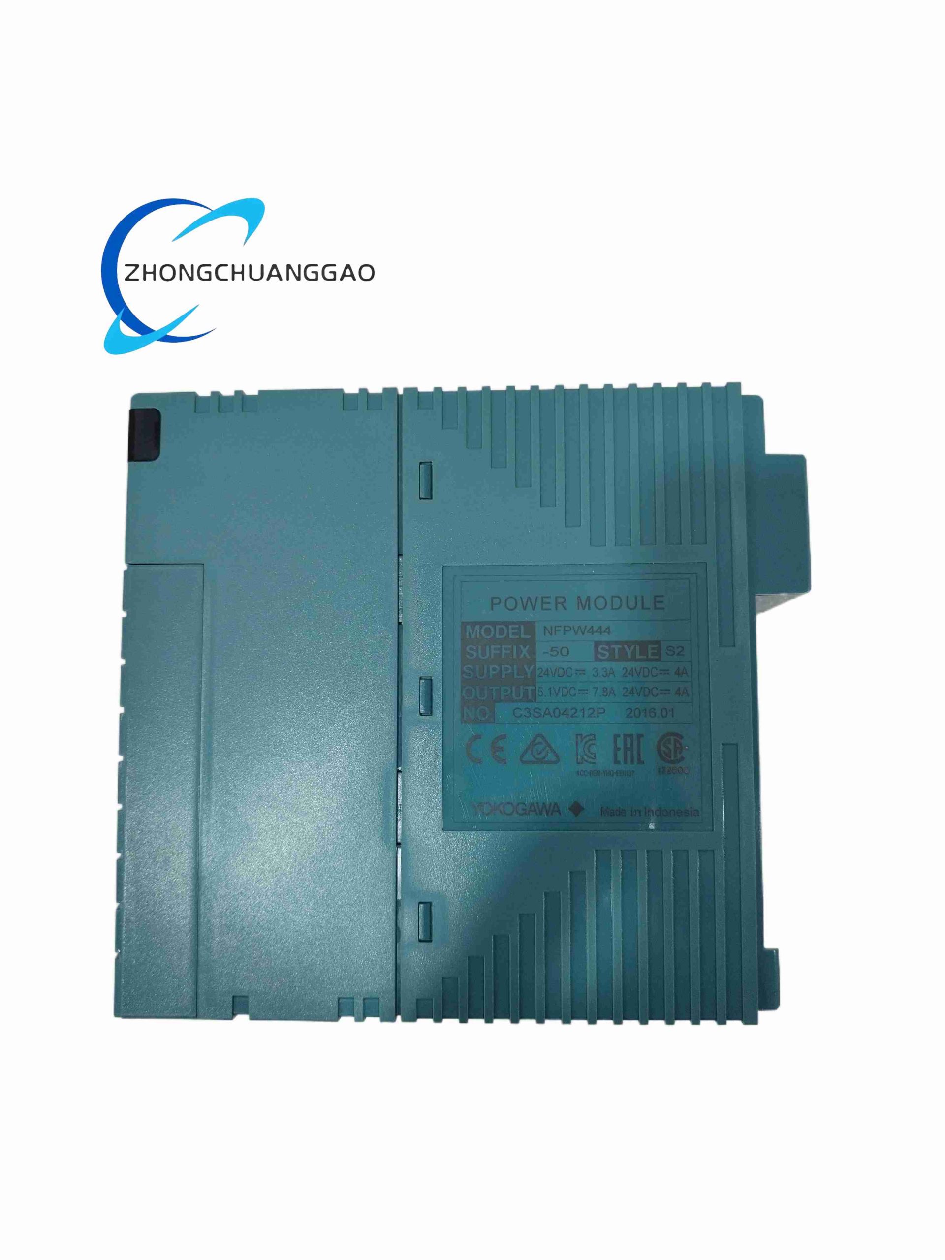
- DC Input Power Range: 21.6V DC ~ 31.2V DC (24V DC nominal input, ±10% fluctuation tolerance)
- Dual Independent Output Power Channels
- Channel 1 (System Logic Power): Rated +5.1V DC, maximum continuous output current 7.8A
- Channel 2 (Field Bus Isolated Power): Isolated 24V DC field power, maximum output current 4A, diode parallel redundant isolation design for duplex power supply configuration
- Total Maximum Output Power: Approximately 42W rated continuous power output
- Reverse Input Voltage Protection: Built-in anti-reverse power diode circuit, no permanent damage if DC input positive/negative wires are reversed during wiring
- Operating Ambient Temperature Range: -40℃ ~ +85℃ ultra-wide industrial temperature range
- Physical Dimensions: 146.5mm × 49.7mm × 130mm standard rack module size
- Net Weight: 0.6kg
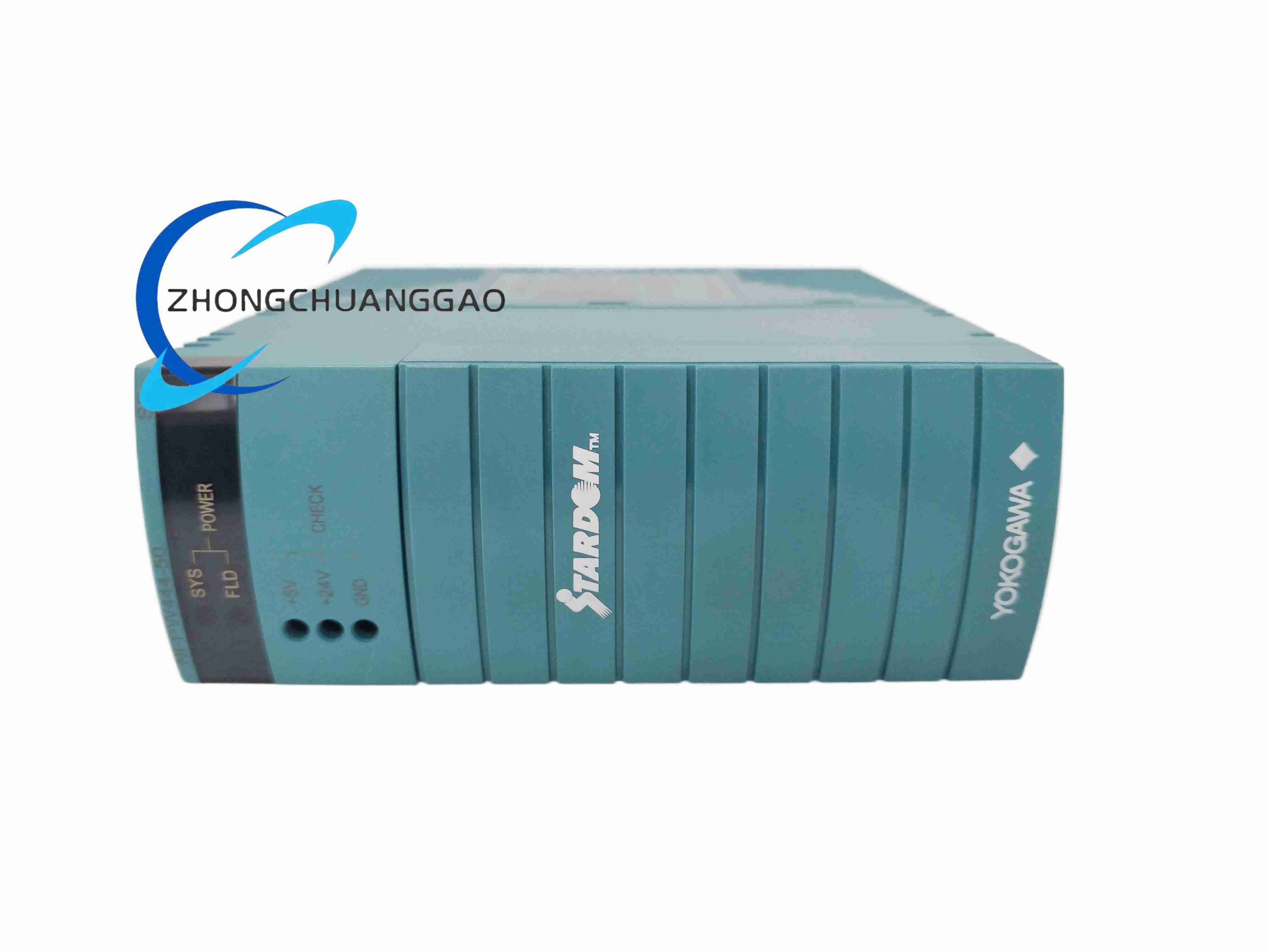
- Status Indicator LEDs: SYS LED (5V system power output status), FLD LED (24V field bus power output status)
- Test Access Terminals: Front panel reserved +5V and +24V voltage test terminals for on-site multimeter voltage measurement without disassembling rack wiring
- Redundancy Duplex Support: Two NFPW444 modules can be installed in parallel redundant mode; internal isolation diodes automatically balance load current between two power supplies
Function & Feature Highlights
- Dual independent isolated power output circuits: separates low-voltage digital logic power for CPU/I/O modules and high-voltage field bus power for FOUNDATION Fieldbus H1 field equipment to eliminate mutual electrical interference between system logic and field communication circuits
- Complete duplex redundant parallel power supply architecture, seamless automatic load balancing between two power modules; single power supply module fault will not cause system power interruption
- Full hot-swap support: faulty power supply module can be pulled out and replaced with spare module while the entire control station remains powered and running continuously
- Built-in multi-layer over-protection circuits: overvoltage protection, overcurrent short-circuit protection, overtemperature thermal shutdown protection; automatically cut off output power when abnormal electrical parameters detected to protect connected CPU and I/O modules from damage
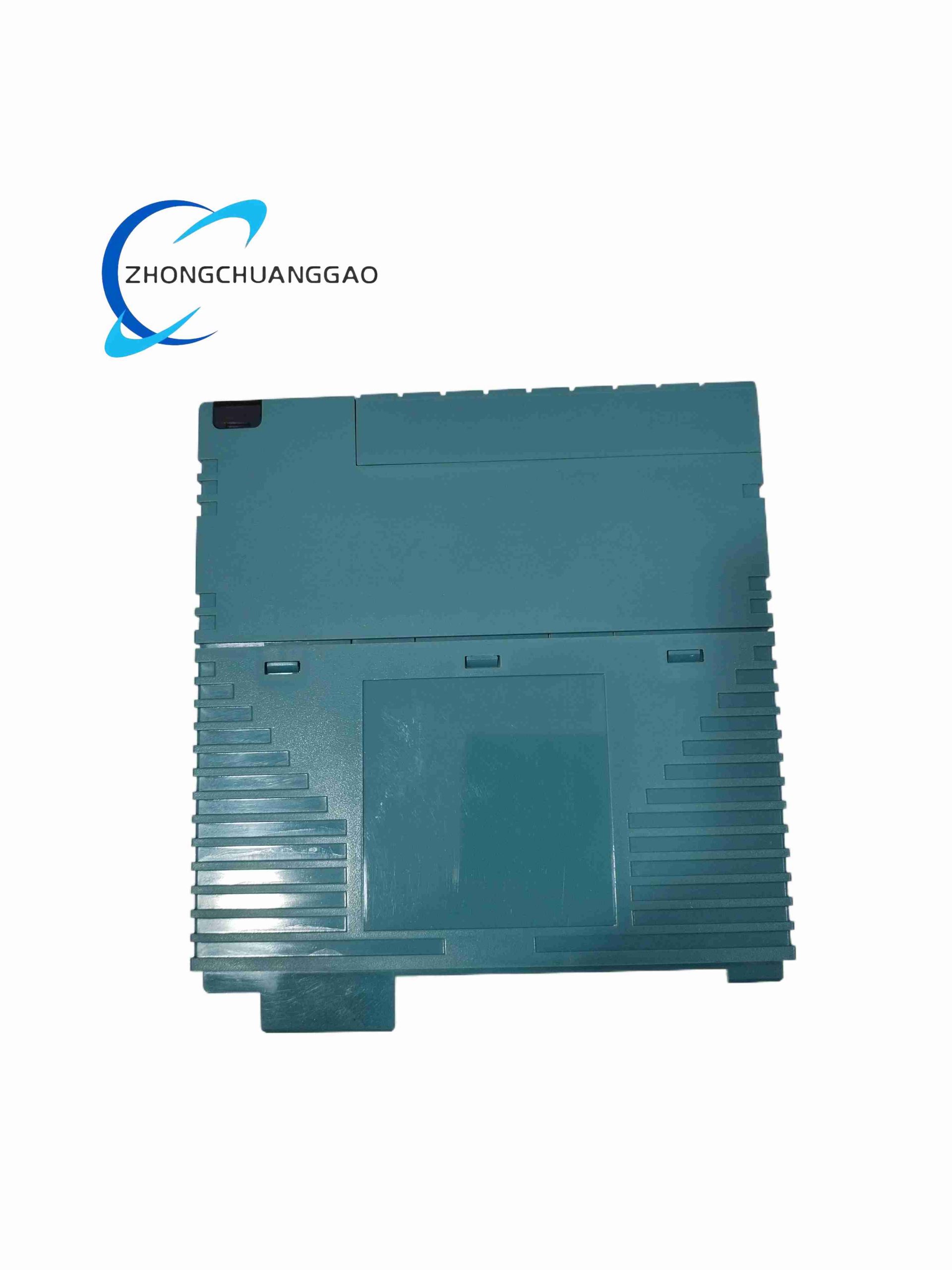
- Fanless passive cooling design with integrated aluminum heat sink on module rear panel; no rotating mechanical fan components to eliminate fan failure risks and reduce long-term maintenance costs
- Complete compatibility with all FCN-100 series CPU modules (including NFCP100-S00 S3) and all analog/digital I/O modules; fully compliant with STARDOM DCS system baseplate power bus communication protocol
- Built-in RAS diagnostic monitoring circuit: continuously monitors input voltage, 5V output voltage, 24V field power voltage and internal heat sink temperature; fault status signal transmitted to CPU module for upper SCADA system fault alarm reporting
Working Principle
The NFPW444 module receives raw 24V DC industrial power from the control cabinet UPS power distribution bus via the baseplate power input busbar. The input power first passes through an EMC filter circuit consisting of inductors and X/Y capacitors to suppress grid transient voltage surges and high-frequency electromagnetic noise. The filtered DC power is split into two independent isolated DC-DC switching power converter circuits inside the module. The first DC-DC converter steps down the input 24V DC to a stable regulated +5.1V DC output, supplied to the baseplate internal power bus to power all CPU, communication and digital I/O logic circuits. The second isolated DC-DC converter maintains regulated 24V DC isolated output power dedicated for FOUNDATION Fieldbus H1 field bus devices, separated by isolation transformers to block common-mode noise between field equipment and control station internal logic circuits. Internal load balancing diodes enable parallel duplex redundant operation of two NFPW444 modules; each power supply automatically shares 50% of total system load current under normal operating conditions. When internal circuit overcurrent, overvoltage or overtemperature fault conditions are detected by the onboard monitoring chip, the power module immediately triggers a soft shutdown protection mechanism to cut off all output power channels, while transmitting a digital fault alarm signal to the system CPU module via the SB local bus.
Material Composition & Structural Features
- Housing Material: Flame-retardant UL94-V0 industrial ABS plastic shell, standard Yokogawa industrial blue color
- Heat Dissipation Structure: Rear panel integrated extruded aluminum alloy heat sink with large-area fin structure for passive heat conduction cooling
- Internal Circuit Board: Multi-layer heavy copper industrial power PCB, high-efficiency DC-DC switching power MOSFET chips, high-capacity low ESR electrolytic filter capacitors, isolation transformers, fast blow overcurrent protection fuses
- Mechanical Rack Structure: Standard vertical pluggable rack module design, front panel locking buckle to fix module tightly on NFBU series baseplate; front panel embedded LED status indicator lamps and exposed voltage test terminals with protective transparent plastic cover
- EMC Shielding Structure: Internal circuit compartments separated by conductive metal shielding plates to isolate high-frequency switching power noise from low-voltage monitoring signal circuits
Installation Requirements
- Rack Mounting Rules: Install vertically on Yokogawa NFBU series FCN control station baseplate, fully insert module connector gold fingers into baseplate power bus socket and lock front panel buckle completely to avoid poor power contact under equipment vibration
- Redundancy Duplex Installation: When configuring redundant power supply system, install two identical NFPW444 modules on adjacent baseplate power slots, connect both module input power terminals to independent UPS power distribution circuits to realize complete power input source redundancy
- Cabinet Heat Dissipation Installation Limits: Maintain minimum 20mm vertical spacing between adjacent power supply modules on the rack to ensure unobstructed natural convection air flow for passive heat sink cooling; do not install heat-generating equipment directly above or below NFPW444 modules
- Input Power Wiring Specification: Use minimum 1.5mm² cross-section copper wire for 24V DC input power wiring; install external circuit breaker (rated 10A) for each power supply module input circuit for short-circuit isolation protection
- Ambient Installation Restrictions: Install only inside indoor sealed electrical control cabinets; avoid installation locations with water splash, corrosive chemical gas, heavy dust accumulation or direct high-temperature heat radiation
Application Scenarios
- Yokogawa STARDOM FCN-100 series distributed DCS control stations for petrochemical, natural gas and refining process plants
- Thermal power plant auxiliary process control cabinets, waste-to-energy power generation field control stations
- Pharmaceutical fine chemical batch production line distributed control system rack power supply
- Offshore oil & gas platform process control station redundant power supply backup system
- Water treatment plant, sewage desalination industrial process monitoring control cabinet power distribution
- Metallurgical mining flotation, smelting furnace process automation control rack power supply
Operation & Maintenance Precautions
- Hot-swap replacement operation must be completed by certified industrial electrical technicians; confirm standby redundant power supply module is fully powered and load-balanced before pulling out faulty module to avoid instantaneous system power dip
- Do not disassemble the plastic housing or aluminum heat sink without authorization; internal high-voltage DC-DC switching power circuits contain dangerous high-current electrical components, disassembly poses electric shock hazard
- Regular monthly inspection of front panel SYS and FLD LED indicators; steady-off LED lamps indicate corresponding power output channel fault, immediately activate spare redundant power module and replace faulty unit during planned equipment maintenance window
- Avoid long-term continuous operation at ambient temperature exceeding +85℃; excessive operating temperature will accelerate electrolytic capacitor aging inside the power module, shorten service life and increase risk of power output instability
- When performing input power wiring modification, fully cut off both redundant power supply input circuit breakers to completely isolate DC power supply before modifying wiring terminals
- Annual preventive maintenance: Clean aluminum rear heat sink surface dust accumulation with compressed dry air to maintain passive heat dissipation efficiency; check baseplate power bus connector gold fingers for oxidation corrosion and poor contact signs
Reviews
There are no reviews yet.