
Product Short Description
Product Introduction

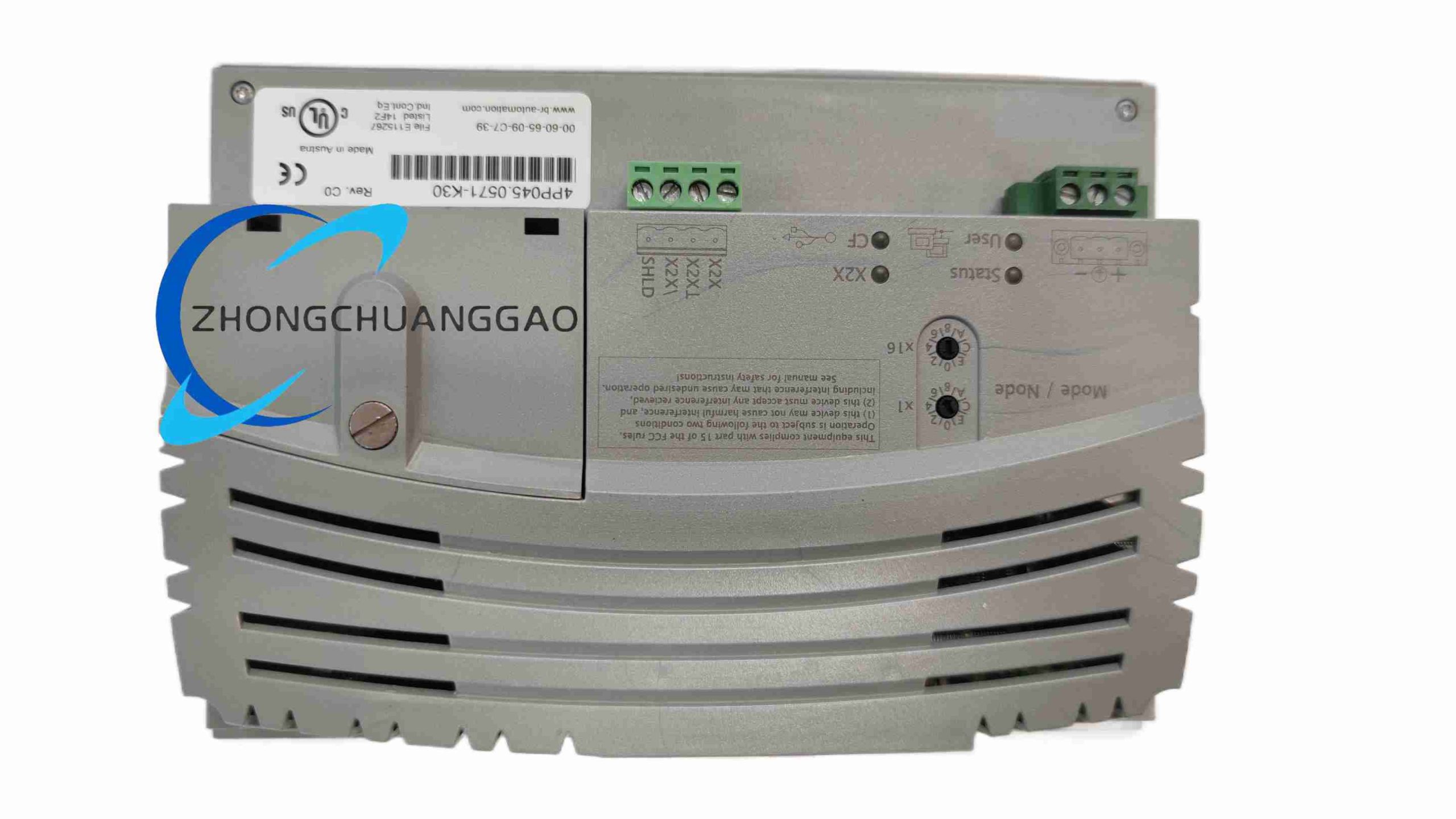
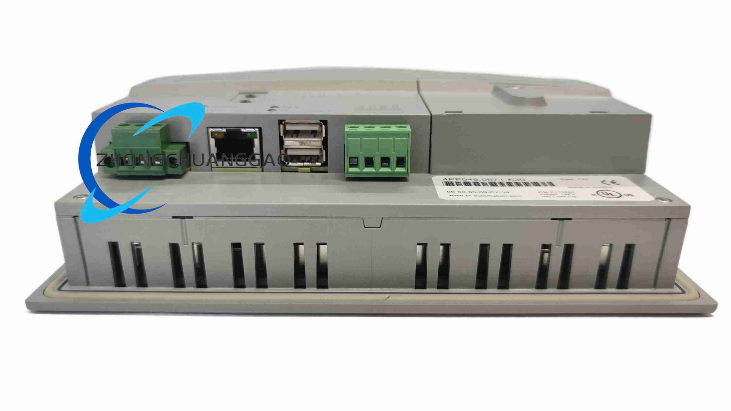
Description
Core Function Features
- All-in-one integrated hardware architecture: Embedded industrial CPU for PLC logic processing, dedicated motion control co-processor, 5.7-inch TFT display and analog resistive touch panel integrated in single unit
- Front panel high protection rating: IP65 dustproof and waterproof splash-proof front panel, suitable for direct installation on machine operation panel without additional protective cover
- Dedicated X2X high-speed real-time motion bus interface: Realize nanosecond-level synchronization control between this unit and B&R servo drives, I/O modules and remote expansion stations
- Multi-channel industrial communication interfaces: 10/100Mbps Ethernet port supporting Modbus TCP, OPC UA, POWERLINK industrial real-time bus; RS232/RS485 serial port supporting Modbus RTU communication
- Onboard digital I/O terminal block: Built-in 16-channel 24VDC digital input and 16-channel relay digital output, supporting direct connection with machine limit switches, indicator lights, solenoid valves and safety signal components
- Real-time Automation Runtime operating system: Independent task scheduling for logic control, motion interpolation and HMI visualization, task cycle adjustable from 100μs to 100ms
- Complete motion control function library: Electronic cam curve interpolation, electronic gearing, flying shear synchronous cutting, multi-axis linear/circular interpolation, spindle positioning and phase synchronization control
- Data storage and backup function: Built-in industrial SD card slot for storing machine programs, production parameter recipes, operation logs and fault historical records; support one-click program backup and recovery
- Multi-color status LED indicators: Independent LED lights for power supply, system running status, communication bus fault, digital I/O channel status and SD card storage access
- Global safety and industry certifications: CE, UL, cULus, TÜV functional safety certification, EAC Eurasian conformity certification
Technical & Performance Specifications
| Parameter | Standard Rated Value |
|---|---|
| Model Full Code | PP045.0571-K30 |
| Display Specification | 5.7-inch TFT color LCD screen, resolution 640×480, 65536 display colors, backlight service life 50000 hours |
| Touch Panel Type | 4-wire analog resistive touch screen, support glove touch operation |
| Core Processing Hardware | Dual-core industrial real-time CPU, independent motion control co-processor |
| Minimum Real-Time Task Cycle | 100 microseconds |
| Onboard Digital I/O | 16×24VDC sinking/sourcing digital input; 16×potential-free relay output (max load 2A per channel) |
| Real-Time Motion Bus | X2X high-speed serial motion bus, synchronization accuracy less than 1μs |
| Communication Interfaces | 1×10/100M Ethernet; 1×RS232/RS485 configurable serial port; X2X bus terminal |
| Storage Medium | Built-in industrial SD card slot, maximum support 32GB industrial grade SD card |
| Rated Supply Voltage | 24VDC, allowable operating voltage range 18VDC ~ 30VDC |
| Rated Power Consumption | Maximum 35W full-load power draw |
| Front Panel Protection Grade | IP65 (dustproof, anti-liquid splash) |
| Rear Wiring Area Protection Grade | IP20 |
| Operating Temperature Range | 0°C ~ +50°C cabinet ambient temperature |
| Storage & Transport Temperature | -20°C ~ +70°C |
| Relative Humidity | 10% ~ 90% non-condensing |
| Cabinet Cutout Installation Size | 160mm (width) × 122mm (height) |
Material Composition & Structural Characteristics
- Front Panel Housing Material: Black high-strength ABS+PC flame-retardant plastic panel (UL94 V-0 fire resistance rating), sealed silicone rubber waterproof sealing ring between front panel and cabinet cutout to achieve IP65 protection
- Internal Mainboard Substrate: High TG FR4 industrial printed circuit board, multi-layer copper shielding structure to suppress internal electromagnetic interference between display, CPU and motion circuits
- Touch Screen Component: Four-wire analog resistive touch film attached to the front of TFT display, hard scratch-resistant surface coating to reduce mechanical abrasion during long-term operation
- Rear Wiring Terminal Components: Spring-cage quick plug terminal blocks for 24VDC power supply, digital I/O signal wiring and X2X bus communication wiring; industrial metal shielding connectors for Ethernet and serial communication ports
- Mechanical Installation Structure: Four embedded metal locking clips on the rear housing for fixed installation on cabinet cutout; no additional mounting brackets required, only tighten locking clip screws to complete installation and sealing
- Physical Dimensions: 172mm (W) × 134mm (H) × 48mm (D); Net weight: 1.15kg
Working Principle
The onboard digital input terminal continuously collects real-time status signals of machine limit switches, safety gates, emergency stop buttons and photoelectric sensors, and transmits all digital signal data to the main CPU for logic judgment processing. The relay digital output channel receives control instructions from the CPU to drive solenoid valves, indicator lights and contactors to execute mechanical action output.
For multi-axis motion control requirements, the unit transmits target position, speed and torque setpoints to external B&R servo drives via X2X real-time motion bus, and receives real-time motor encoder feedback data returned by servo drives. The dedicated motion co-processor independently completes high-speed closed-loop servo algorithm calculation and trajectory interpolation, realizing microsecond-level synchronous coordination control of multiple motion axes.
The resistive touch panel continuously samples touch coordinate signals, transmits touch operation coordinates to the HMI visualization task of the main CPU, completes page switching, parameter modification, equipment start-stop operation and other human-machine interaction functions according to touch instructions. All equipment operation data, fault alarm information and production parameter changes are automatically stored in the SD card for later data query, equipment failure analysis and production data statistics.
Installation Requirements
- Cabinet Cutout Installation Standard: Cut the operation panel cabinet according to standard size 160mm×122mm; clean all burrs and sharp edges of the cutout to avoid scratching the front panel silicone sealing ring; insert the unit from the front of the cabinet cutout, tighten four rear locking clip screws evenly to ensure the silicone sealing ring is fully compressed to maintain IP65 front panel protection performance
- Cabinet Environmental Requirements: Install in electrical control cabinet with internal ambient temperature maintained between 0°C ~ +50°C; avoid installation in areas with direct sunlight irradiation, high-temperature heat source radiation or heavy oil mist and conductive metal dust; install cabinet exhaust cooling fans if cabinet internal temperature exceeds 40°C for long-term operation
- Power Wiring Specifications: Use 0.75mm² ~ 1.5mm² multi-strand copper shielded wire for 24VDC power supply wiring; connect the negative terminal of the 24V power supply to the cabinet PE protective earth ground bar to eliminate electrostatic interference on the touch panel; torque spring-cage terminal blocks to 0.6N·m to ensure wiring contact stability
- Communication Bus Wiring Rules: All X2X motion bus, Ethernet and RS485 serial communication wiring must use dedicated industrial shielded twisted-pair cable; the cable shielding layer is grounded to the cabinet PE ground bar at a single end only to prevent ground loop noise interference; separate communication signal wiring and high-power servo drive motor power cables with minimum 12cm horizontal routing clearance
- Digital I/O Wiring Specifications: Use 0.5mm² multi-strand copper wire for digital input and output channel wiring; all safety signal wiring (emergency stop, safety gate) must use independent wiring harnesses separated from ordinary I/O signal wiring to avoid signal interference causing safety function failure
Reviews
There are no reviews yet.