
Product Short Description
Product Overview
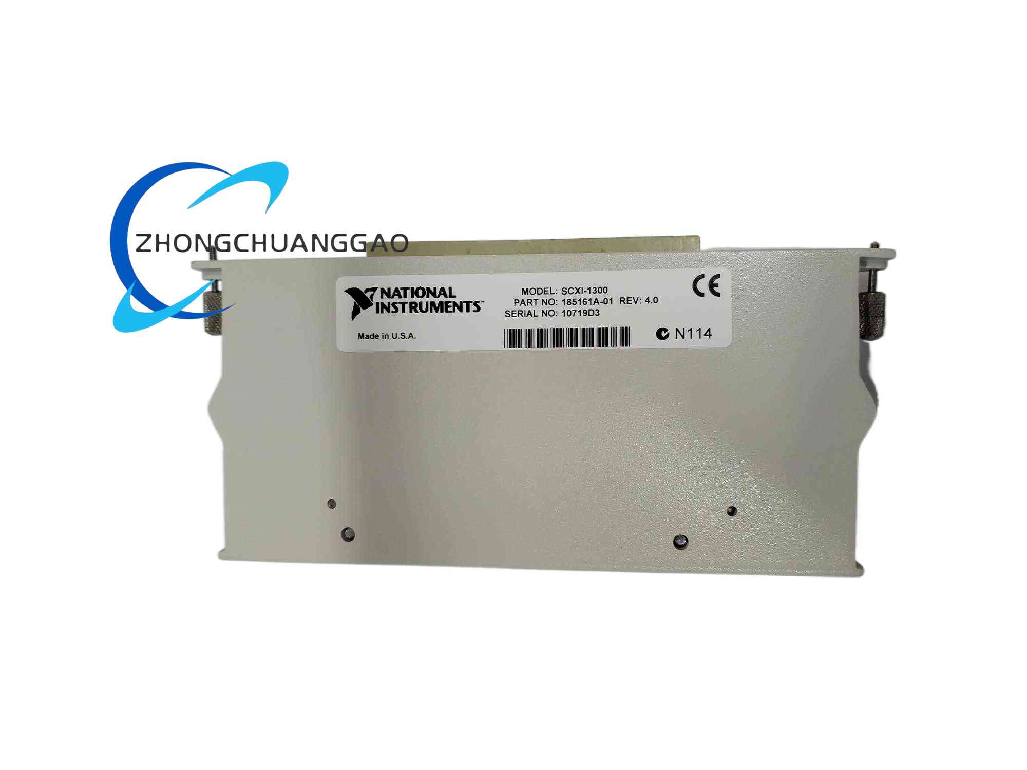
The SCXI-1300 is a front-mount screw terminal block accessory exclusively designed to mate with NI SCXI 32-channel differential analog input signal conditioning modules, fully compatible with the SCXI-1104C analog input module. It provides standardized screw terminals for convenient field sensor and analog signal wiring connection, integrating a built-in cold-junction compensation temperature sensor for thermocouple measurement compensation, and complete strain relief structure to fix signal wires and prevent wiring loosening from cabinet vibration.
Description
Electrical Parameters
- Total Screw Terminals: 72 independent screw terminals
- Signal Channel Terminals: 32 pairs of differential signal positive/negative terminals, directly mapped to the 32 differential input channels of SCXI-1104C
- Auxiliary Function Terminals: Chassis ground screw terminals, module AOREF analog output reference terminal, SCXIbus GUARD shielding compensation terminal
- Integrated CJC Temperature Sensor: Built-in precision thermistor cold-junction compensation sensor
- CJC Measurement Accuracy: ±1.3 °C across 0~50°C operating temperature range
- CJC Repeatability Error: ±0.5 °C
- CJC Output Signal: 0–0.5 V DC temperature proportional voltage signal
- Rated Wiring Wire Gauge: 14–26 AWG solid/stranded copper wire
- Screw Terminal Torque Specification: 5–7 inch-pounds tightening torque
Environmental & Physical
- Operating Temperature: 0°C ~ 50°C
- Storage Temperature: -20°C ~ 70°C
- Relative Humidity: 10% ~ 90% non-condensing
- Mechanical Dimensions: Matches standard SCXI module front panel mounting size
Functional Features
- Full Channel Signal Wiring Interface: 32 pairs of differential screw terminals directly correspond to all 32 input channels of SCXI-1104C, supporting direct connection of differential analog sensor signals without intermediate adapter wiring.
- Integrated Cold-Junction Compensation Sensor: Built-in precision thermistor CJC sensor for thermocouple signal cold-junction temperature compensation, eliminating thermocouple measurement error caused by terminal block ambient temperature variation.
- Complete Auxiliary Ground & Shield Terminals: Independent chassis protective earth ground terminals, analog reference voltage terminals and bus shielding guard terminals, supporting standardized signal shielding and grounding wiring to suppress common-mode noise and ground loop interference.
- Built-In Wire Strain Relief Mechanism: Equipped with removable strain-relief bar and strain-relief fixing screws, all field signal wires pass through the strain-relief opening before connecting to screw terminals; eliminates wire pulling force loosening screw terminal connections under cabinet vibration or cable tension.
- Detachable Protective Cover: Hinged plastic protective cover fully covers all live screw terminals after wiring completion, preventing accidental short-circuit between adjacent signal wires caused by foreign conductive debris or human accidental contact.
- Direct Plug-And-Mate SCXI Module Interface: Rear mating connector precisely aligns with the front I/O connector of SCXI analog input modules; fixed by two top/bottom locking thumbscrews, quick assembly and disassembly without specialized tools.
Working Principle
Field analog differential signals output from industrial sensors, transmitters or voltage sources are stripped to the specified wire insulation length and inserted fully into the corresponding positive/negative screw terminal pairs on the SCXI-1300 terminal block, then secured by tightening the terminal screws to the specified torque. The rear mating connector of the terminal block transmits each differential signal pair directly to the corresponding input channel circuit of the mated SCXI-1104C analog input module. The onboard cold-junction thermistor continuously measures the ambient temperature of the terminal block surface and outputs a proportional analog voltage signal to the SCXI module, which the DAQ measurement software uses to calculate and compensate thermocouple temperature measurement error induced by cold junction temperature drift. All chassis ground and shielding wiring connected to the auxiliary ground terminals provides a low-resistance grounding path to eliminate electromagnetic noise interference in weak analog signal wiring.
Material & Structural Characteristics
- Terminal Block Base Housing: High-strength flame-retardant ABS plastic base with UL94-V0 fire resistance rating, impact-resistant and corrosion-resistant for industrial cabinet continuous operation.
- Screw Terminal Hardware: Tin-plated brass screw terminals and clamping wire jaws, excellent electrical conductivity, anti-oxidation and anti-corrosion in high-humidity cabinet environments; flat-head steel tightening screws with standardized torque control.
- Protective Cover & Strain Relief Components: Transparent flame-retardant ABS plastic hinged protective cover; removable flame-retardant plastic strain-relief bar with metal fixing screws.
- Internal Circuit & CJC Sensor: Precision glass-encapsulated thermistor cold-junction compensation sensor fixed to the terminal block base near the signal screw terminals to accurately capture terminal block ambient temperature; short gold-plated internal PCB traces connecting screw terminals to the rear mating connector.
- Mating Connector Assembly: Molded plastic rear connector housing with gold-plated copper contact pins for low-resistance electrical contact with the SCXI module front I/O connector; two metal thumbscrews for locking the terminal block to the SCXI module front panel.
Installation Requirements
- Module Compatibility Restriction: Only compatible with NI SCXI 32-channel differential analog input modules (SCXI-1104C); cannot mate with digital relay or RF multiplexer SCXI modules.
- Pre-Wiring Preparation: Strip signal wire insulation to a maximum length of 7 mm; excessive exposed bare wire will create adjacent terminal short-circuit hazards after cover installation.
- Strain Relief Installation Sequence: Install the strain-relief bar first, route all signal wires through the strain-relief opening, then connect stripped wire ends to screw terminals and tighten screws to 5–7 in-lb torque.
- Mating Locking Procedure: Align the rear connector of the SCXI-1300 with the front I/O connector of the SCXI-1104C module, fully insert the mating connector, then manually tighten the top and bottom thumbscrews to lock the terminal block firmly to the module front panel.
- Ground Wiring Specification: Run a minimum 1.5 mm² copper ground wire from the dedicated chassis ground screw terminal to the control cabinet protective earth ground bar to establish a low-impedance noise suppression grounding path.
- Post-Wiring Inspection: After completing all signal wiring and tightening terminal screws, close the protective cover and fasten the cover fixing screws to block live terminal exposure.
Application Scenarios
- Multi-channel industrial analog voltage signal acquisition systems paired with SCXI-1104C modules.
- Temperature measurement systems using thermocouple sensors requiring cold-junction temperature compensation.
- Power distribution cabinet secondary analog signal monitoring wiring terminals.
- Laboratory multi-sensor differential signal test bench standardized wiring interface.
- Solar, battery pack multi-point voltage monitoring field wiring terminal accessory.
Operation & Usage Precautions
- Screw Torque Control Warning: Do not over-tighten terminal screws beyond 7 in-lb torque; excessive torque will crack the plastic terminal base and deform brass wire clamping jaws, causing poor electrical contact. Do not under-tighten screws below 5 in-lb torque; loose wires will generate unstable signal noise and intermittent open-circuit faults during cabinet vibration.
- Bare Wire Short-Circuit Prevention: Ensure no excess bare copper wire extends past the screw terminal clamping jaw after wiring; exposed bare wire between adjacent terminals creates permanent short-circuit risks when conductive dust accumulates inside the terminal block cover.
- Wiring Modification Power Cut Rule: All signal wire installation, disconnection or rewiring must be performed after fully cutting off the SCXI chassis power supply to avoid live wire contact causing electric shock or analog signal surge damage to the mated SCXI-1104C module circuits.
- Strain Relief Mandatory Use: Never skip installing the strain-relief bar after completing wiring; external cable pulling tension will directly pull signal wires loose from screw terminals under long-term cabinet vibration or cable movement.
- Cleaning Maintenance Restrictions: Only clean dust and debris from the terminal block using soft non-metallic anti-static brushes; never use conductive cleaning sprays, water or liquid solvents to wipe screw terminals, which will cause terminal oxidation and electrical short-circuit failure.
- High-Voltage Signal Isolation: When connecting high-voltage analog signals (up to ±60 VDC) to the terminal block, ensure all signal wire insulation voltage rating is ≥300 V Cat II; avoid bundling high-voltage signal wiring together with low-voltage weak sensor wiring inside the cabinet without metal shielding separation.
Reviews
There are no reviews yet.