
Product Short Description
Product Overview
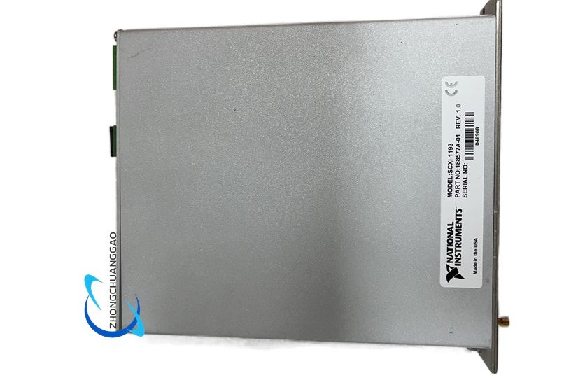
The SCXI-1193 is a high-performance RF signal multiplexing switch module developed for the NI SCXI chassis measurement system, designed for high-frequency analog signal routing and channel switching in automated RF test benches. It features 32 independent RF signal channels and 4 common COM ports, supporting multiple software-configurable signal routing topologies including unterminated multiplexers, externally terminated multiplexers and flexible sparse matrix routing architectures.
Description
RF Signal Performance Parameters
- Total RF Input Channels: 32 independent signal channels
- Common COM Ports: 4 shared COM signal output ports
- Rated Operating Bandwidth: DC to 500 MHz
- Supported Configurable Topologies: Dual 8×1 terminated multiplexer, 16×1 / 32×1 unterminated multiplexer, quad 3×1 multiplexer, independent sparse matrix routing
- Characteristic Impedance Matching: 50 Ω RF system impedance matching, supports external 50 Ω MCX terminator installation
- Relay Settling Time: Fixed relay mechanical settling delay for high-frequency signal stability
- Power-On Default State: All relays open, default topology set to quad 8×1 multiplexer
Environmental & Physical
- Operating Temperature: 0°C ~ 50°C
- Storage Temperature: -20°C ~ 70°C
- Relative Humidity: 10% ~ 90% non-condensing
- Form Factor: Standard single-width SCXI plug-in module
Functional Features
- Wide-Band High-Frequency Signal Support: 500 MHz full RF bandwidth supports low-frequency analog signals, audio frequency signals, radio frequency test signals for electronic component validation.
- Multi-Topology Software Configurable Routing: Users can switch between multiple multiplexer and matrix routing architectures purely through software programming without any hardware jumper modification, adapting to diverse RF test workflow requirements.
- 50 Ω Impedance Matching Design: Supports external 50 Ω MCX terminators for terminated multiplexer topologies to eliminate high-frequency signal reflection and standing wave distortion during channel switching.
- Full Automated Test Software Integration: All relay channel open/close operations are controllable via niSwitch driver APIs and LabVIEW graphical programming, seamlessly integrated into automated RF test sequence scripts for semiconductor, communication device validation.
- Multi-Chassis System Scalability: Multiple SCXI chassis equipped with SCXI-1193 modules can be cascaded to expand total RF test channels for large multi-DUT (Device Under Test) automated test benches.
- Advanced Relay Reset Algorithms: Equipped with two software reset algorithms (simple reset, advanced reset) to reliably reset all relay channels and restore the default routing topology after test scan abortion or system fault recovery.
Working Principle
High-frequency RF test signals from DUTs, signal generators or reference instruments are connected to the 32 front RF channel terminals of the module. Onboard high-frequency RF relays control the connection between each independent signal channel and the four shared COM output ports. The host test hardware sends routing command signals via the SCXI backplane bus to the module’s onboard logic control circuit, which parses the target channel-to-COM routing instructions and triggers the corresponding RF relay to close, establishing a high-frequency signal transmission path between the selected input channel and the assigned COM port. The COM port routes the multiplexed RF signal out to measurement instruments (oscilloscope, spectrum analyzer) for signal acquisition and analysis. The 50 Ω external terminator absorbs reflected high-frequency signal energy to eliminate signal distortion caused by impedance mismatch in RF transmission lines.
Material & Structural Characteristics
- Shielded RF Enclosure: Thickened aluminum alloy fully sealed shielding casing with internal RF absorbing foam, minimizes high-frequency signal leakage and external electromagnetic interference that distorts RF measurement results.
- RF Circuit Substrate: Low-loss high-frequency RF PCB board with controlled 50 Ω transmission line impedance, gold-plated RF contact traces to reduce high-frequency signal insertion loss.
- Core Switch Components: Miniature high-frequency RF coaxial relays with low insertion loss and high isolation between disconnected channels; internal RF signal absorbing resistors for impedance matching auxiliary circuits.
- Connector Hardware: Gold-plated SCXI backplane control bus connector; front panel MCX RF signal terminal mating interface with low-reflection 50 Ω impedance matched contacts.
- Mechanical Vibration Suppression: Single-slot SCXI plug-in design locked by front thumbscrews; all RF relays and PCB boards fixed with silicone shock-absorbing gaskets to prevent vibration-induced RF contact impedance drift.
Installation Requirements
- Chassis Compatibility: Install into NI SCXI series chassis (SCXI-1000, SCXI-1001, SCXI-1000DC).
- RF Terminator Matching: For terminated multiplexer topologies, install NI 50 Ω MCX external terminators to all odd-numbered RF channels before connecting test signal wiring.
- RF Wiring Standard: Use 50 Ω impedance matched shielded RF coaxial cables for all test signal wiring; avoid using un-matched general twisted-pair wires which cause severe high-frequency signal reflection and attenuation.
- Cabinet EMI Shielding: Install the chassis inside a metal shielded test cabinet to block external radio frequency interference (wireless signals, high-power switching power supplies) from contaminating RF measurement signals.
- Grounding Specification: Connect the module’s chassis ground lug to the cabinet’s RF reference earth ground with wide flat copper grounding straps to minimize RF ground loop noise.
- Environmental Limits: Continuous operation ambient temperature limited to 0~50°C; strictly avoid water vapor, oil mist and corrosive gas inside the shielded RF test cabinet to prevent RF relay contact oxidation and PCB transmission line corrosion.
Application Scenarios
- Semiconductor component automated RF test benches: RF filter, antenna, RF amplifier multi-DUT channel switching for signal performance characterization.
- Communication equipment validation testing: Bluetooth, Wi-Fi, radio frequency transceiver module multi-channel signal scanning measurement.
- Electronic lab high-frequency signal measurement: Oscilloscope, arbitrary waveform generator multi-channel signal routing for automated parameter testing.
- Aerospace & defense electronic component testing: High-frequency radar auxiliary circuit multi-point signal monitoring and automated fault scanning.
- Consumer electronics production line testing: Audio equipment, wireless smart device multi-channel RF performance batch automated testing.
Operation & Usage Precautions
- Impedance Mismatch Warning: Never use non-50 Ω general wiring or skip external terminators when running terminated multiplexer topologies; severe high-frequency signal reflection will cause measurement data distortion and damage connected RF test instruments.
- RF Power Input Limitation: Do not input high-power RF signal sources to the module’s RF channels; excessive RF input power will burn internal RF relay contact components.
- Power Off Rule for Wiring Modification: All RF coaxial cable installation, disconnection and modification must be completed after cutting off the SCXI chassis power supply and all connected RF test instruments power to avoid electrostatic discharge damaging sensitive RF relay circuits.
- Relay Mechanical Lifetime Control: Avoid continuous rapid repeated relay switching in automated test scripts; excessive mechanical actuation accelerates relay contact wear and increases RF signal insertion loss over long-term use.
- Electrostatic Discharge (ESD) Protection: Before touching the module’s RF terminals or internal circuit boards, wear anti-static wristbands connected to cabinet earth ground; static electricity will permanently damage sensitive RF relay components.
- Cabinet Humidity Control: Maintain low humidity inside the shielded RF test cabinet; high humidity oxidizes gold-plated RF relay contacts, increasing signal loss and causing unstable RF measurement results.
Reviews
There are no reviews yet.