
Product Short Description
Product Overview
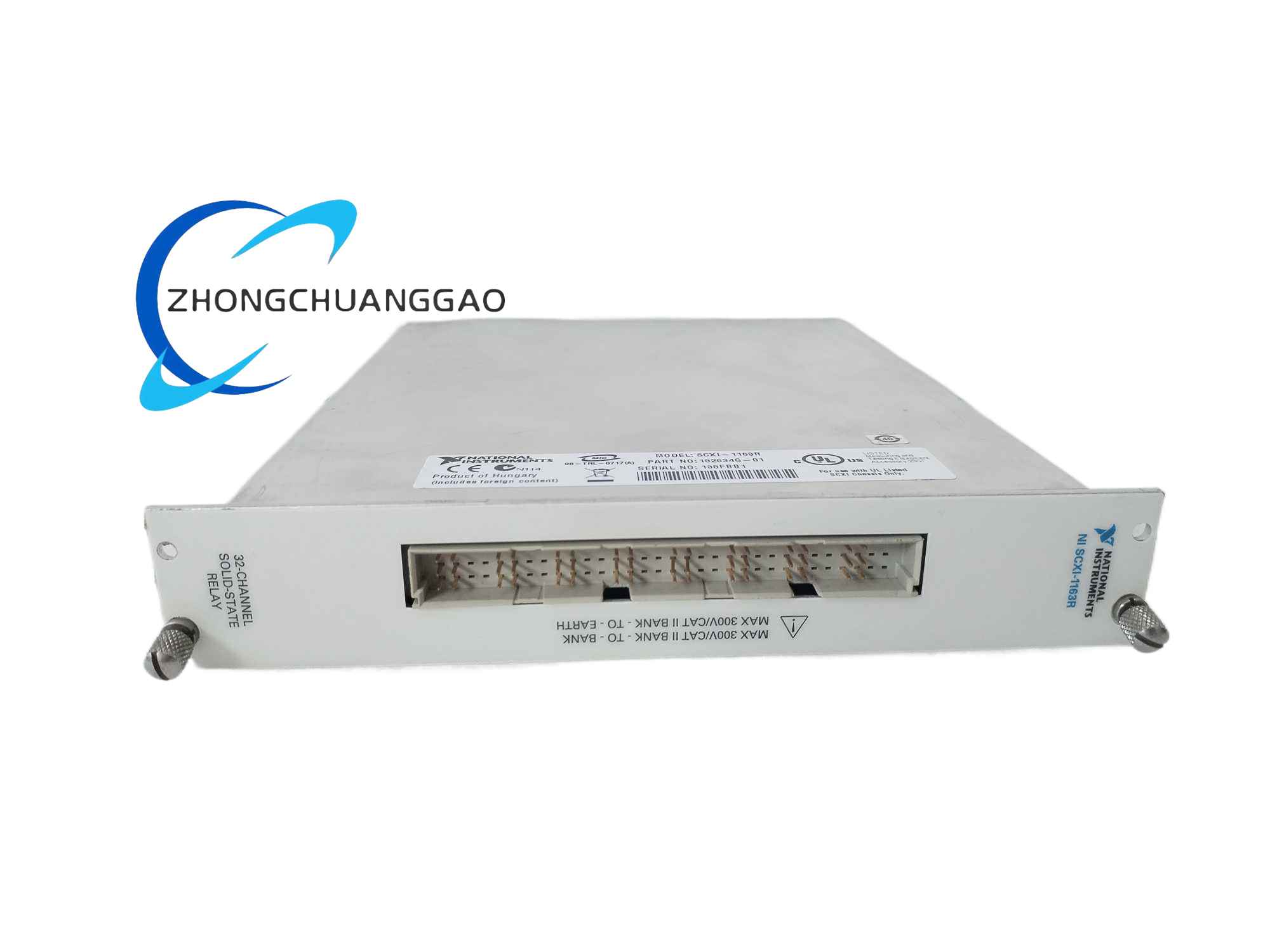
The SCXI-1163R is a high-density isolated solid-state relay switch module designed for the NI SCXI chassis system, dedicated to software-controlled switching of industrial AC/DC high-voltage load devices. It integrates 32 independent normally-open solid-state relays separated into 8 banks of 4 relays each, with full optical isolation between control logic circuits and field load circuits. The module supports two operation modes: serial SCXI bus control mode for integration into multi-module DAQ systems, and parallel direct DIO control mode for independent digital I/O hardware connection.
Description
Electrical Relay & Switch Parameters
- Total Relay Channels: 32 independent Form A (normally open) solid-state relays
- Bank Layout: 8 banks × 4 relays per bank, each bank equipped with a shared common pole terminal
- Maximum Switching Load Rating: 240 V AC RMS / 240 V DC, maximum continuous load current 200 mA per channel
- Isolation Rating: Full optical isolation between control side and load side; 250 V RMS isolation voltage between relay banks and bank-to-chassis ground
- Maximum Switching Speed: 750 relay operation cycles per second
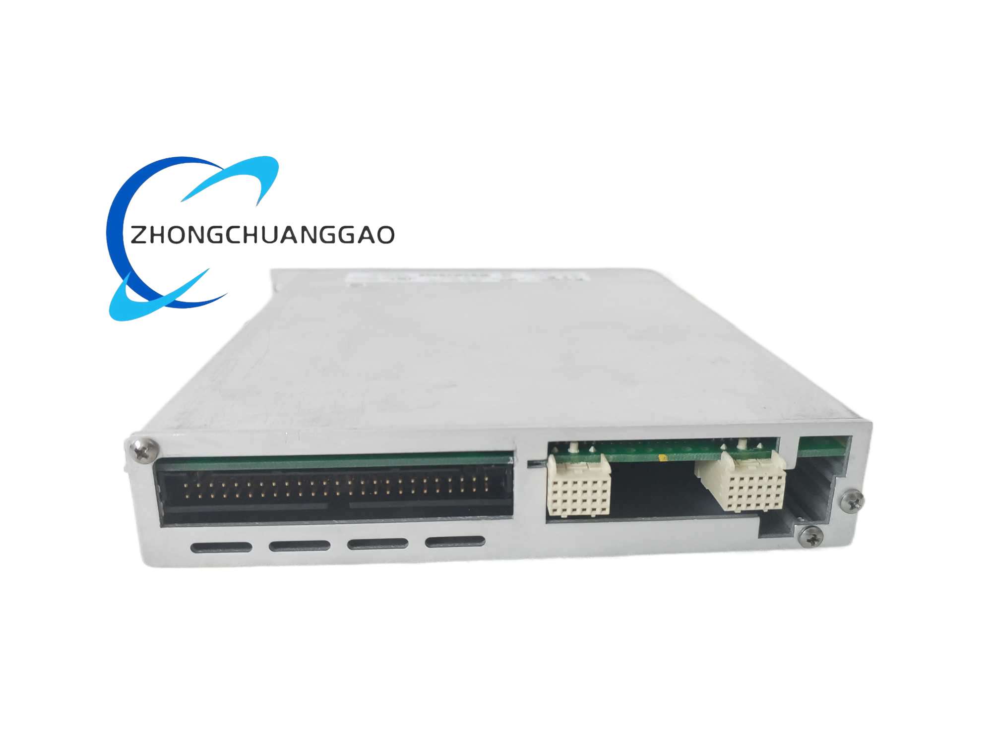
- Control Logic Interface: Serial mode via SCXI backplane bus; parallel mode via rear 50-pin digital I/O connector
- Jumper Configurable Modes: Serial multi-chassis mode, single chassis serial mode, parallel DIO direct control mode
Environmental & Physical
- Operating Temperature: 0°C ~ 50°C
- Storage Temperature: -20°C ~ 70°C
- Relative Humidity: 10% ~ 90% non-condensing
- Form Factor: Standard single-width SCXI plug-in module
Functional Features
- High-Density Isolated Switching: 32 independent solid-state relays eliminate mechanical relay contact wear, achieving long-lifetime silent switching without mechanical bounce noise.
- Complete Optical Isolation Barrier: Each relay channel uses independent optocoupler isolation, completely isolating low-voltage computer control circuits from high-voltage industrial field loads, eliminating ground loop risks and electric shock hazards.
- Dual Operation Modes: Serial bus mode allows seamless integration into large SCXI multi-module measurement and control systems; parallel mode enables direct connection to standalone digital I/O hardware for independent small-scale control applications.
- Software Full Controllability: All relay open/close operations are fully programmable through NI DAQmx and niSwitch driver APIs, compatible with LabVIEW, LabWindows/CVI, Measurement Studio programming environments.
- Configurable Jumper Settings: Onboard user-adjustable jumpers support flexible configuration for single chassis, cascaded multi-chassis and parallel DIO control architectures without hardware modification.
- Multi-Bank Separation Design: Relays are divided into 8 electrically separated banks; each bank supports independent VCC and GND power supply wiring for mixed voltage load control (AC and DC loads in the same module).
Working Principle
The host DAQ or DIO hardware transmits digital switch control commands to the SCXI-1163R via the SCXI backplane bus (serial mode) or rear parallel digital connector (parallel mode). The onboard logic decoding circuit parses channel switch commands and drives the input side of each channel’s optocoupler. When the optocoupler is energized, the solid-state relay semiconductor switch on the load side is turned on, connecting the field load device to its power supply. When the control signal is cut off, the optocoupler de-energizes, the solid-state relay cuts off the load circuit. The optical isolation layer completely blocks electrical conduction between the low-voltage control circuit and high-voltage load circuit, preventing field circuit surges from damaging the host DAQ hardware.
Material & Structural Characteristics
- Outer Shielded Housing: Aluminum alloy extrusion casing with matte anti-corrosion oxidation coating, provides full electromagnetic shielding to suppress cabinet EMI interference affecting relay switching stability.
- Circuit Board: High TG FR4 industrial PCB with double-sided acrylic conformal coating, resistant to dust, moisture and light oil mist in control cabinets.
- Core Switch Components: Zero-crossing trigger solid-state relay chips with built-in surge absorption TVS diodes; high-speed linear optocouplers for channel isolation.
- Connector Hardware: Gold-plated copper alloy rear SCXI bus connector and rear 50-pin parallel DIO connector; front panel terminal block mating interface with gold-plated contact pins for low-resistance wiring contact.
- Mechanical Structure: Single-slot SCXI chassis plug-in design, locked via front panel thumbscrews; internal circuit boards fixed with shock-absorbing silicone pads to resist cabinet vibration-induced solder joint loosening.
Installation Requirements
- Chassis Compatibility: Install into standard NI SCXI chassis (SCXI-1000, SCXI-1001, SCXI-1000DC).
- Jumper Configuration Pre-Installation: Adjust onboard W2, W3, W4, W5, W6 configuration jumpers according to the target system architecture (single chassis serial, multi-chassis cascaded serial, parallel DIO mode) before inserting the module into the chassis slot.
- Terminal Block Matching: Must pair with SCXI-1326 high-voltage screw terminal block for field AC/DC load wiring connection.
- Field Wiring Standard: Use wire gauge 14–26 AWG with insulation voltage rating ≥300 V Cat II; separate AC high-voltage load wiring and low-voltage control wiring inside the cabinet with metal shielding partitions.
- Power Load Calculation: Calculate total load current of all active relay channels; ensure the load power supply has sufficient current margin to avoid voltage drop and relay switching failure.
- Grounding Specification: Connect module chassis ground lug to cabinet protective earth ground with 1.5 mm² copper ground wire to discharge transient voltage surges from field load circuits.
- Cabinet Environmental Limits: Install inside sealed industrial control cabinet with dust filter; avoid direct exposure to water, oil mist, corrosive gas; continuous operating ambient temperature limited to 0~50°C.
Application Scenarios
- Industrial automation field device control: Solenoid valve on/off switching, indicator light/beacon control, small motor power switching, conveyor auxiliary actuator control.
- Power system test bench control: Secondary circuit relay switching, power supply channel selection, load bank switching control.
- Laboratory automated test equipment: Automated fixture switching, test signal path selection, sample station actuator control.
- Building automation control: HVAC damper actuator switching, lighting zone group control, fire alarm auxiliary relay output.
- Energy equipment monitoring systems: Solar inverter auxiliary contact control, battery pack protection relay switching.
Operation & Usage Precautions
- Load Current Limitation Warning: Never exceed 200 mA continuous current per relay channel; overcurrent will permanently burn out solid-state relay semiconductor chips.
- Inductive Load Surge Suppression: When switching inductive loads (solenoid valves, small motors), install external freewheeling diode (DC loads) or RC absorption snubber (AC loads) in parallel with the load terminals to suppress inductive voltage surges that damage the module’s internal circuits.
- Wiring Power Cut Mandate: All field load wiring installation, modification and disconnection must be completed after cutting off both SCXI chassis control power and field load power supply to avoid electric shock and module circuit burnout.
- Mode Jumper Modification Rule: Always power off the entire SCXI chassis before adjusting onboard configuration jumpers; modifying jumpers under powered state will short internal logic circuits and permanently damage the module.
- Humidity & Condensation Prevention: High-humidity cabinet environments require cabinet dehumidifiers; PCB condensation will cause relay channel short-circuit failure.
- EMI Separation Rule: Do not route high-current AC power cables parallel to the module’s signal wiring for long distances; electromagnetic interference will cause false relay trigger errors.
Reviews
There are no reviews yet.