
Description
Product Overview
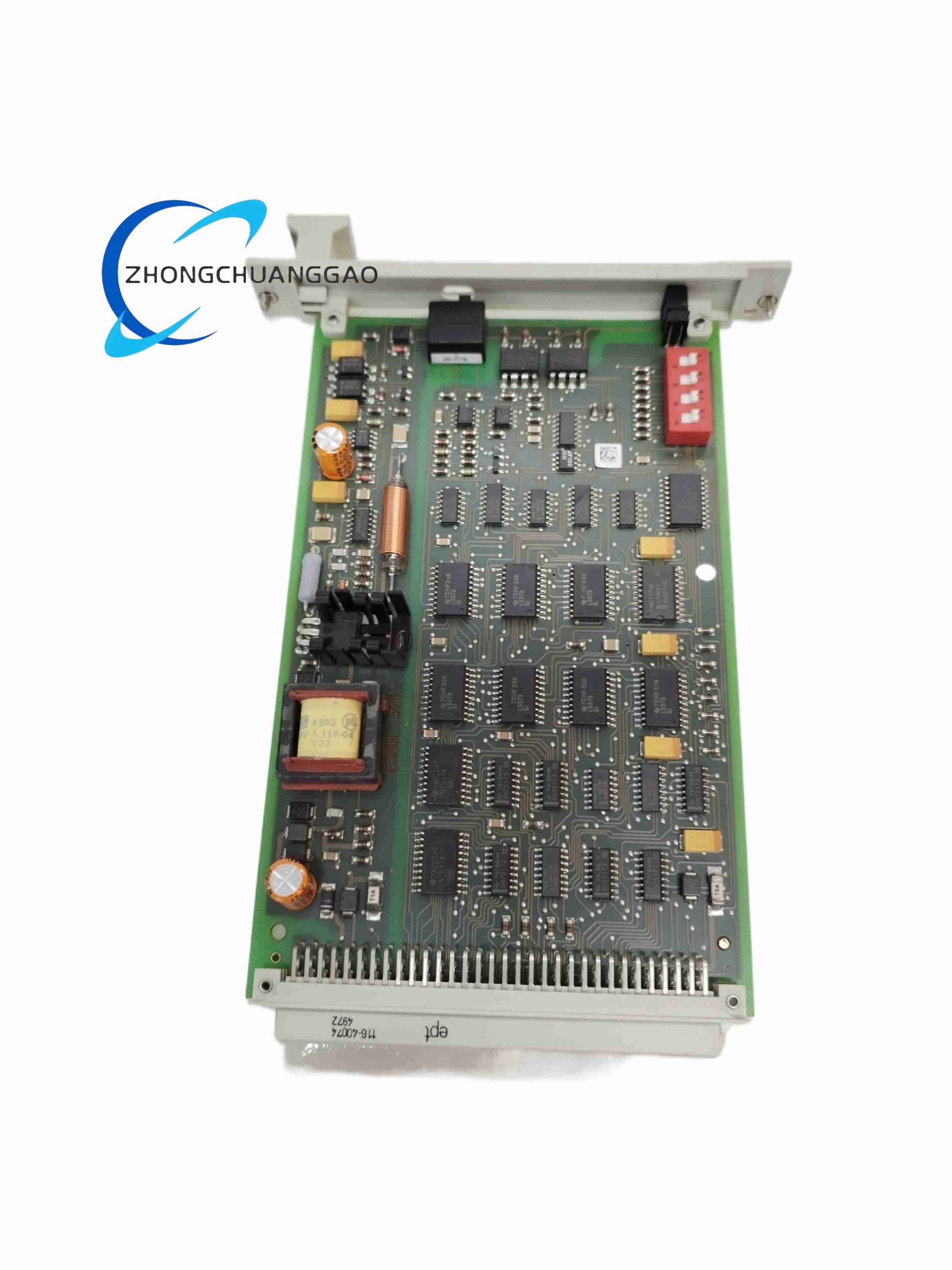
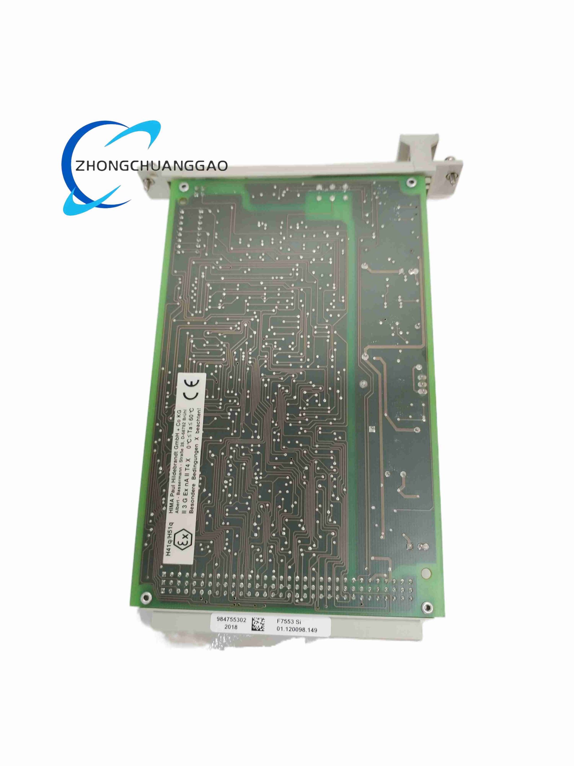
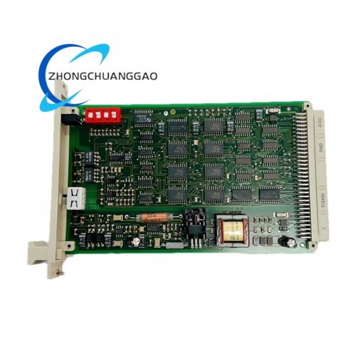
HIMA F7553 is a galvanically isolated bus coupling hardware exclusively deployed for HIMax safety control platforms. It serves as the physical communication bridge between central safety CPU racks and distributed remote I/O subracks, delivering fail-safe signal transmission, cross-circuit electrical separation, and system fault containment for SIL-rated safety loops including ESD, F&G, and burner management systems. The module eliminates cross-talk interference between multi-rack safety bus segments and prevents fault cascading across discrete I/O subracks.
Technical Specifications
- Dimension: Standard 4 TE Eurocard width; outer size 100 mm × 75 mm × 35 mm
- Net Weight: 0.14 kg
- Primary Power Input: 5 V DC, nominal draw 600 mA
- Auxiliary Power Input: 24 V DC, nominal draw 750 mA
- Communication Bus Protocol: Proprietary HIMax internal safety redundant bus
- Galvanic Isolation Voltage Rating: 2500 V AC between bus segments
- Operating Temperature Range: 0 °C to +60 °C
- Storage Temperature Range: -40 °C to +85 °C
- Electromagnetic Compliance: EN 61000-6-2 industrial heavy EMC standard
- Safety Certification: IEC 61508 SIL 3, IEC 61511 Process Safety, ISO 13849-1 PL d
- Max Supported Subracks per F7553: 4 remote I/O subracks
Function Features
- Full galvanic isolation between host rack bus and remote subrack bus channels
- Real-time continuous bus line diagnostic for short-circuit, open-circuit, and ground fault
- Fail-safe default state: cut off remote bus communication upon detected hardware fault
- Signal level adaptation for long-distance safety bus wiring up to 300 meters
- Built-in LED status indicators for power supply, bus active status, and fault alarm
- Bidirectional safety data transmission with parity error correction for all bus frames
- Fault propagation blocking: local subrack short-circuit cannot damage central controller rack
Performance Parameters
- Bus signal scan latency: ≤ 12 ms per connected I/O subrack
- Diagnostic coverage rate for bus faults: 99.6%
- Mean Time To Dangerous Failure (MTTFd): > 2,200,000 hours under rated operating conditions
- Continuous 24/7 operation duty cycle: 100% non-stop rated
- Signal transmission bit error rate (BER): < 1 × 10⁻¹²
Material Composition
- Main Circuit Board: FR4 flame-retardant printed circuit board with tin-lead free copper traces
- Front Panel Housing: Reinforced ABS industrial flame retardant plastic, UL94-V0 grade
- Connector Terminal Blocks: Nickel-plated copper alloy contact pins, PA66 insulating base
- Internal Passive Components: Industrial-grade polypropylene capacitors, metal film resistors
- Mounting Hardware: Galvanized carbon steel DIN rail locking clips
Structural Characteristics
- Standard Eurocard vertical rack plug-in structure, rear side DIN 41612 bus connector interface
- Single-slot 4 TE compact form factor with front-panel locking lever for vibration resistance
- Front panel with three independent LED indicator windows (Power, Bus Run, Fault)
- Internal double-layer shielding foil separating analog power circuits and digital bus circuits
- Fully sealed internal component cavity to resist dust ingress (IP20 cabinet rating)
Working Principle
The module receives differential safety bus signals from the central controller rack via the primary bus connector, processes signal level matching and electrical isolation through optocoupler isolation arrays, then forwards cleaned differential bus signals to remote I/O subracks. A dedicated fault monitoring ASIC continuously samples bus voltage, current, and frame parity; upon detecting any abnormal electrical condition, the isolation switches activate to disconnect the faulty bus segment instantly and trigger front-panel fault LED alarm. All transmitted safety data frames include dual parity check bits verified on both input and output bus sides.
Advantage Highlights
- SIL3 certified isolation eliminates cross-circuit safety fault risks in multi-rack SIS layouts
- Compact 4 TE footprint reduces cabinet space occupation for multi-subrack expansion
- Full real-time bus diagnostics minimize troubleshooting downtime during plant maintenance
- Vibration-resistant locking structure suitable for onshore and offshore heavy vibration industrial sites
- Long-distance bus signal amplification removes distance limitation for distributed field I/O layouts
- Zero cross-talk performance guarantees stable safety logic execution under heavy EMC interference
Applicable Industries
Petrochemical refining, natural gas processing, offshore oil & gas platforms, power generation thermal plants, chemical batch manufacturing, fertilizer production, pulp & paper mills, pharmaceutical safety interlock systems, turbine safety control facilities
Installation Requirements
- Install exclusively on standard 35 mm DIN rail inside IP20 industrial control cabinets
- Maintain minimum 15 mm vertical ventilation gap above and below the module
- External 24 V DC power supply must include 10 A time-lag T-type slow blow fuse protection
- Bus wiring must use shielded twisted pair cable with cable shield single-end grounding at host rack only
- Mount rack in non-corrosive ambient environment with relative humidity 5% – 90% non-condensing
- No external heat source within 300 mm horizontal radius of the module mounting position
Usage Precautions
- Hot-swapping operation is prohibited; cut off full rack power before inserting or removing F7553
- Do not connect non-HIMax compatible I/O subracks to the module remote bus port
- Avoid wiring remote bus cables alongside high-power AC motor cables to prevent EMC interference
- Regular quarterly inspection of front-panel LED fault indicators for hidden bus degradation
- Store spare modules in anti-static ESD shielding bags at controlled 20 °C ambient temperature
- Do not operate the module outside the 0 °C to +60 °C rated operating temperature window
Reviews
There are no reviews yet.