
Product Short Description
Product Brief Introduction
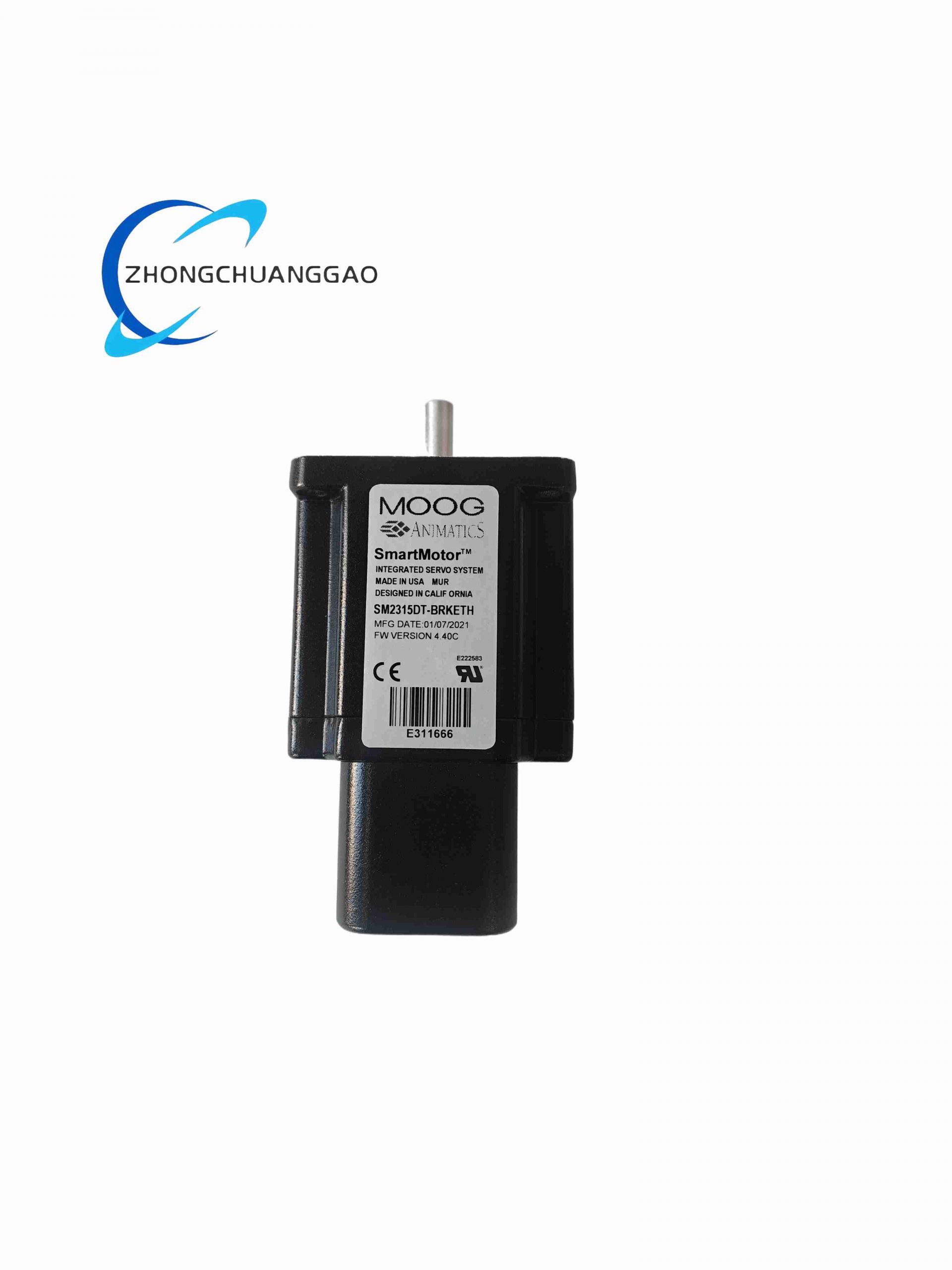
The SM2315DT-BRKETH is a high-performance compact integrated servo motor from Moog SM series, integrating high-torque brushless stator, electromagnetic holding brake, 23-bit absolute multi-turn encoder, built-in servo drive power stage and EtherCAT industrial Ethernet communication port within a single compact housing. It eliminates separate servo drive cabinet layout, reduces wiring quantity and cabinet space occupation, engineered for high precision, high dynamic response and compact machinery installation space constraints, widely used in high-end automation requiring zero position retention after power cut.
Description
Core Technical Specifications
- Mechanical Frame Size: NEMA 23 integrated servo motor form factor
- Rated Input Voltage: 48VDC industrial low voltage bus power supply
- Rated Continuous Torque: 1.5 N·m
- Peak Overload Torque: 4.5 N·m (300% overload, sustainable for 3 seconds)
- Rated Speed: 3000 RPM continuous operating speed
- Maximum No-Load Speed: 4500 RPM
- Built-in Holding Brake: 24VDC electromagnetic spring brake, static holding torque 1.8 N·m
- Encoder Resolution: 23-bit multi-turn absolute magnetic encoder, no battery backup required
- Communication Interface: Onboard EtherCAT (CoE DS402 protocol) Ethernet port, dual RJ45 for daisy-chain connection
- Control Loops: Position loop, velocity loop, torque loop fully closed-loop control inside motor
- Digital I/O Terminals: 4×24VDC sinking digital inputs, 2×24VDC sourcing digital outputs
- PWM Switching Frequency: 16kHz high-frequency current loop
- Operating Temperature Range: -20°C ~ +50°C full rated torque output; torque derating mandatory above 50°C
- Protection Rating: IP65 motor main body, IP54 cable connector area
- Shaft Configuration: Standard 8mm smooth output shaft, optional keyway shaft customization
- Weight: 1.2 kg
- Dimension: 76mm flange width, total motor body length 118mm
Function Features
- All-in-one integrated design: servo power drive, encoder, brake, communication circuit integrated into motor housing, no external servo amplifier needed
- Dual EtherCAT RJ45 connectors support daisy-chain multi-motor wiring, greatly simplify cabinet wiring layout
- Built-in 23-bit absolute multi-turn encoder, retains absolute position data permanently without backup battery, zero homing required after power restart
- Independent electromagnetic holding brake module, instant locking of motor shaft once power supply is cut off to prevent load sliding and position loss
- Complete built-in motion functions: electronic gearing, electronic cam, point-to-point positioning, homing sequence, velocity profiling
- Full set of hardware self-protection mechanisms: overcurrent, overvoltage, undervoltage, over-temperature, encoder signal loss, brake drive fault, stall protection
- Ultra-low cogging torque design, less than 1% of rated torque, achieves ultra-smooth low-speed stable operation without vibration
- Support STO Safe Torque Off safety signal input, meets PLd SIL2 machine safety standard requirements
Working Principle
External 48VDC DC bus power enters the internal power conversion circuit of the integrated motor, and the embedded 32-bit motion DSP receives real-time motion instructions from upper master controller via EtherCAT Ethernet bus. The DSP executes high-speed vector control algorithm to drive internal power MOSFET module to output three-phase sine wave current to the brushless stator winding, generating rotating magnetic field to drive rotor operation. The 23-bit magnetic absolute encoder continuously feeds back real-time rotor multi-turn position and speed data to the internal control chip to form fully closed-loop position adjustment. When equipment power is disconnected or brake trigger signal is sent, the 24VDC brake coil power supply cuts off, internal spring structure pushes friction plate to lock the motor output shaft to maintain load position. All motion parameter configurations, fault diagnosis and data uploading are transmitted bidirectionally through the onboard EtherCAT communication port without additional signal wiring.
Material Composition
- Motor Housing: High-strength extruded aluminum alloy shell with black hard anodized anti-corrosion coating, built-in radial heat dissipation fins
- Stator & Rotor Core: High silicon low-loss silicon steel sheet laminated stack, high-energy rare earth neodymium iron boron permanent magnet attached to rotor surface
- Brake Assembly: High wear resistance copper alloy friction disc, stainless steel compression spring, enameled copper brake coil
- Encoder Unit: Magnetic induction encoder chip, stainless steel encoder target wheel, anti-vibration plastic packaging shell
- Internal Drive PCB: Multi-layer high-density SMD circuit board with conformal coating for dust and moisture resistance
- Output Shaft: 42CrMo alloy steel quenched and tempered shaft with anti-rust passivation treatment
- Cable Connectors: IP65 metal locking aviation plug connectors with silicone sealing gaskets
Structural Characteristics
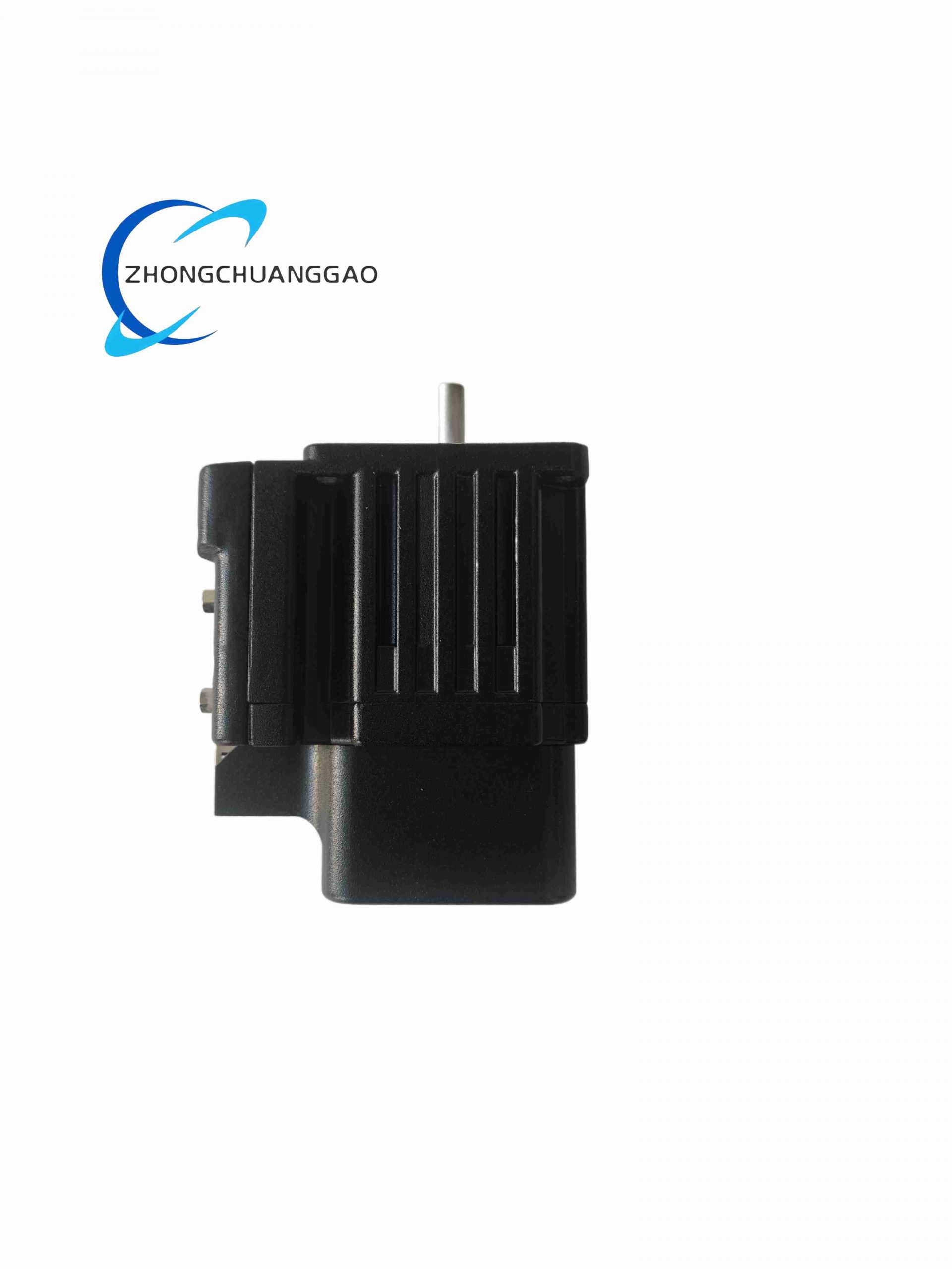
- Compact NEMA23 integrated body structure, split layout: front brake section, middle stator motor section, rear integrated drive & encoder section
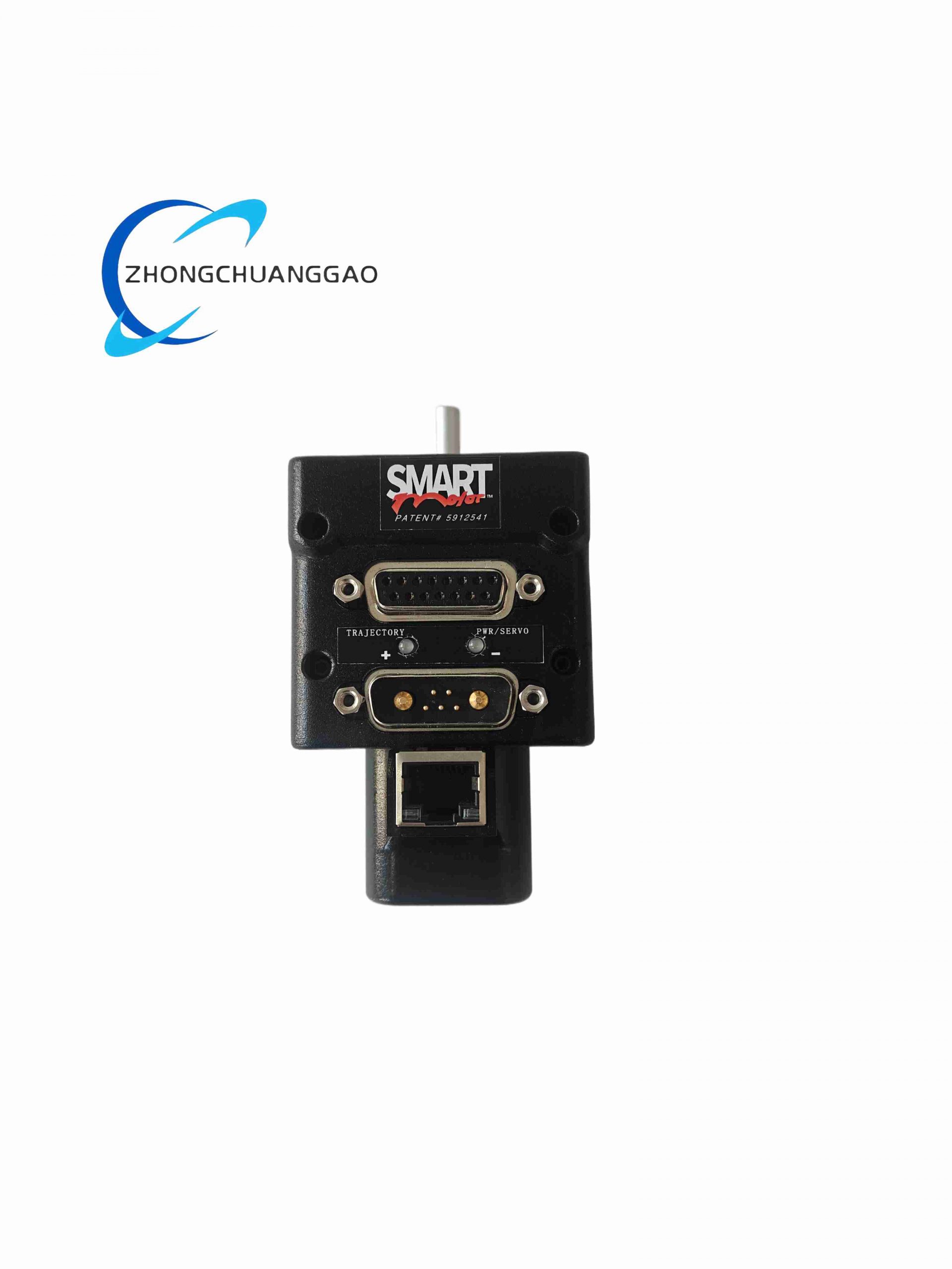
- Dual RJ45 Ethernet ports arranged on the rear side for series daisy-chain connection of multiple motors
- Side aviation plug terminals separately arranged for DC power supply, brake power and digital I/O signal wiring, classified wiring to avoid signal interference
- Outer shell integrated radial heat dissipation fins to realize passive air convection heat dissipation without auxiliary fan
- Rear panel multi-color LED status indicators: power supply status, EtherCAT communication link, motor running state, fault alarm, brake engagement status
- Flange mounting hole standard NEMA23 specification, compatible with universal linear modules, ball screw actuators and rotary positioning platforms
- Built-in internal EMC filter circuit to suppress high-frequency electromagnetic radiation generated by power switching
Installation Requirements
- Install horizontally or vertically on mechanical equipment flange surface, ensure full contact between motor flange and mounting base to guarantee heat conduction
- Reserve minimum 50mm clearance around motor housing for air circulation heat dissipation, avoid sealing the motor in fully enclosed narrow space
- Use shielded double-core cable for 48VDC power supply wiring, cable shield single-point grounded at equipment metal frame
- EtherCAT communication cable must adopt industrial CAT6A shielded Ethernet cable, maximum single cable transmission distance limited to 100 meters
- Separate power cable and Ethernet communication cable wiring routes, maintain minimum 10cm spacing to prevent power switching noise interfering with high-speed communication
- The 24VDC brake power supply must be independently wired, cannot share power supply with motor main DC bus to avoid voltage drop causing insufficient holding torque
- When multiple motors are connected in EtherCAT daisy chain, the last motor’s spare RJ45 port must be equipped with 120Ω terminal matching resistor
Application Scenarios
- 3C electronic precision assembly equipment: chip mounter, PCB routing machine, micro-component pressing positioning axis
- Automated optical inspection equipment: high-speed linear scanning platform, optical focusing servo axis
- Medical automation equipment: medical sample transfer manipulator, surgical auxiliary positioning actuator
- Precision laboratory test equipment: multi-axis linear motion test bench, constant torque loading test stand
- Small high-speed packaging machinery: labeling head, cutting positioning servo, vertical filling lifting axis
Operation & Maintenance Precautions
- Do not disassemble the integrated motor housing without professional authorization; disassembly will damage internal encoder and drive circuit, void factory warranty
- After cutting off the 48VDC main power supply, wait at least 3 minutes for internal DC bus capacitance to fully discharge before plugging or unplugging aviation connectors
- The electromagnetic brake is only used for static load holding; it is forbidden to rely on the brake to decelerate running motor, which will cause rapid wear of friction disc
- Regularly check the tightness of aviation plug locking ring every 6 months in dusty workshop environments to prevent dust and water vapor ingress from connector gaps
- If over-temperature fault alarm appears, stop continuous high-load operation and check whether the surrounding heat dissipation space is blocked by debris
- Do not apply impact force to the motor output shaft during installation and transportation; strong impact will damage the internal absolute encoder magnetic target wheel and cause permanent position reading failure
- Store spare motors in constant temperature and low humidity environment, storage temperature range -30°C ~ +70°C, avoid long-term exposure to high humidity or corrosive gas environment
Consolidated Supplementary General Notes for All 10 Industrial Products
Universal Installation Rules
- All listed I/O modules, servo drives and integrated motors are designed for indoor cabinet/mechanical installation only; most carry IP20 cabinet-only rating except Moog SM2315DT-BRKETH with IP65 motor body.
- Shielded twisted pair or shielded industrial cables are mandatory for all signal, communication and power wiring to comply with EMC industrial anti-interference standards.
- Single-point grounding rule applies to all cable shielding layers; multi-point grounding will create ground loops and trigger measurement faults or motion jitter.
- Maintain specified ventilation clearance around heat-generating equipment (servo drives, power supply modules) to avoid over-temperature derating or permanent thermal damage.
Universal Troubleshooting & Maintenance Guidelines
- Before any wiring disassembly, fully cut off all AC/DC power supplies and wait for residual capacitance discharge time specified for each product.
- Periodic routine inspection cycles vary by environment: clean terminals and heat sinks every 3 months for dusty factories, every 6 months for clean indoor workshops, every 1 month for marine/chemical corrosive environments.
- All safety-certified equipment (SIL3 SLS1508, STO servo drives, marine SLIO-02) requires regular functional safety testing per corresponding industry standards (IEC 61508, DNV-GL marine rules).
- Any modification to internal circuit, conformal coating, safety wiring or original housing will invalidate product certification and safety protection performance.
- Discontinued legacy equipment (INCA CHLORIDE SG-1124-4) has no cross-model replacement solution; spare parts inventory management is required for long-term system operation.
Universal Environmental Restrictions
- All products cannot be directly exposed to corrosive media including chlorine vapor, salt fog, acid mist, flammable dust without sealed protective cabinets.
- Condensing humidity inside cabinets will cause PCB corrosion, short circuit and signal drift; dehumidification equipment is required for high-humidity workshop, marine and water treatment sites.
- High vibration working sites (ships, forging machinery) must adopt anti-vibration mounting accessories and conduct quarterly wiring looseness inspection.
Reviews
There are no reviews yet.