
Product Short Description
Product Overview
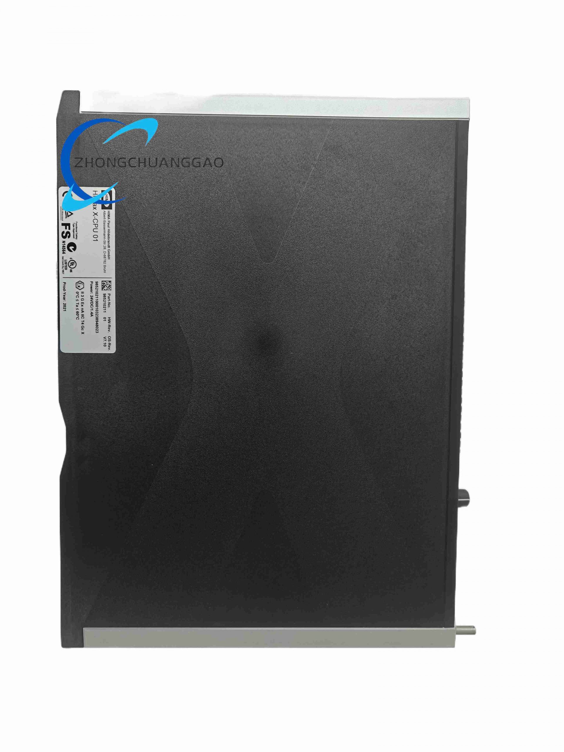
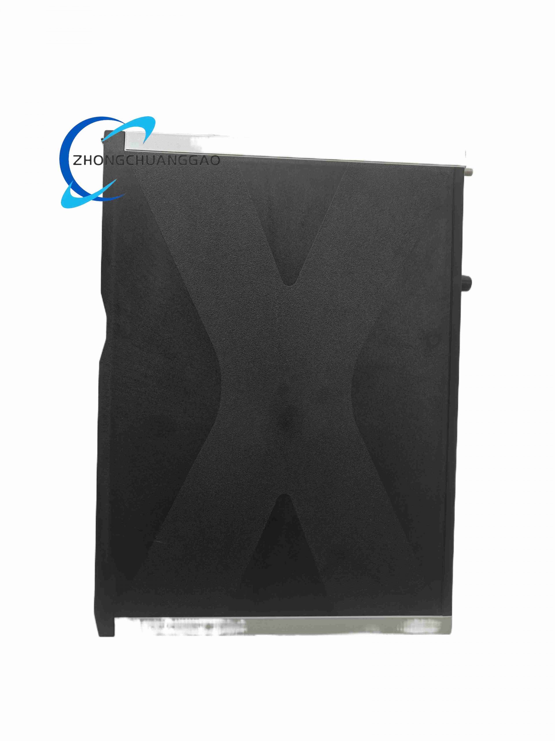
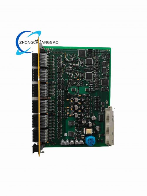
The core master control module of the HIMax safety instrument system, adopting 1-out-of-2 dual redundant safety processor architecture to eliminate single-point control failure. It executes all safety logic programs, collects digital/analog signal data from I/O modules, calculates safety interlock logic, and outputs protection commands to field actuators. All internal logic operations meet SIL 3 functional safety standards, supporting redundant hot backup and seamless master-slave switching without process signal loss.
Description
Technical Specifications
- Processing Core: Dual independent PowerPC safety processors, synchronous dual-channel logic calculation
- Memory Configuration: 128 MB Flash EPROM firmware storage, 256 MB DDRAM real-time data cache, non-volatile NVRAM for variable data retention after power failure
- Program Capacity: Max 1023 kB user safety program memory per logic partition
- Power Input: 24 V DC (-15% ~ +20%), rated input current 1.4 A, built-in 7.5 A overcurrent fuse
- Backplane Bus: Dual redundant high-speed safety XBus, transmission rate 100 Mbps
- Onboard Interfaces: 2 integrated Ethernet switch ports for redundant upper network connection, mode selection toggle switch on front panel
- Safety Level: IEC 61508 SIL 3, IEC 61511 process industry safety certified
- Dimension: 140 mm × 80 mm × 30 mm, weight 0.7 kg
- Operating Environment: -20 ℃ ~ +65 ℃ operating temperature; -40 ℃ ~ +85 ℃ storage; humidity 5%~95% non-condensing
- Switching Speed of Redundancy: Master-slave switch completion ≤ 20 ms without logic interruption
Core Functional Features
- 1oo2 dual-core synchronous calculation, mutual comparison of all logic operation results; inconsistent output triggers safety fault stop
- Full-range self-diagnosis covering processor core, memory, bus circuit and peripheral I/O communication
- Hot redundant backup configuration, automatic master-slave switching upon main CPU hardware failure
- Complete real-time process data archiving, supporting historical curve recording of safety variables
- Multi-partition safety program management, isolated operation of different unit interlock logics
- Hardware watchdog timer, forced safety shutdown when program runaways or deadlocks occur
- Synchronized time calibration with X-COM01 communication module for unified system timestamp
- Front panel multi-color LED indicators for power, run status, fault, redundancy state and bus communication
Working Principle
Two independent PowerPC processors load identical safety logic programs simultaneously and execute all arithmetic and interlock operations synchronously. Every calculation result is cross-compared between dual cores; if deviation exceeds allowable threshold, the module immediately activates safety fail-safe state and cuts off all field output control signals. The main CPU transmits real-time I/O signal data and logic operation results to X-COM01 via dual XBus for external uploading, while receiving configuration instructions from engineering software. The backup CPU keeps full data synchronization with the master in real time; once the master CPU reports hardware fault, the backup takes over all control functions within 20 ms without process interruption. After power failure, NVRAM retains all critical safety variable data for automatic recovery after power restoration.
Structural & Material Characteristics
- Housing: Thickened aluminum alloy anti-interference shell, integrated heat sink ribs for passive heat dissipation
- PCB: Double-sided full-shield FR4 high-temperature resistant circuit board, separate power, analog and digital wiring layers
- Internal layout: Two completely isolated processor circuit cavities to avoid mutual interference between dual cores
- Terminal contacts: Gold-plated backplane edge connectors with wear-resistant coating for long-term plugging
- Front panel: Impact-resistant ABS plastic with dust-proof transparent window for LED observation
Installation Requirements
- Installed on the fixed main slot of HIMax baseplate; redundant configuration requires two X-CPU 01 modules inserted into paired CPU slots
- Ensure vertical air circulation above and below the module, minimum 25 mm clearance for heat dissipation
- Cabinet must be reliably grounded, ground wire cross-section ≥ 2.5 mm² copper wire
- Do not install near frequency converters, high-power contactors or other strong electromagnetic interference sources
- System power supply must use isolated 24 V DC safety power, independent from field equipment power
Application Scenarios
Petrochemical emergency shutdown systems, thermal power boiler protection, gas turbine safety interlock, oil pipeline pressure protection, chemical reactor over-temperature/over-pressure safety control, LNG storage tank fire protection systems.
Operation & Maintenance Precautions
- Program download and modification must be completed under maintenance permission mode to prevent accidental safety logic changes
- For redundant CPU configuration, only replace one module at a time; simultaneous removal of two CPUs causes full system shutdown
- Avoid frequent power cycle of the safety cabinet; repeated power surges accelerate aging of CPU memory chips
- Conduct full logic verification test after every firmware upgrade or program modification before switching to online operation
- Regularly clean the ventilation gap of the module shell every 6 months to prevent dust accumulation leading to overheating faults
Reviews
There are no reviews yet.