
Product Short Description
Product Introduction
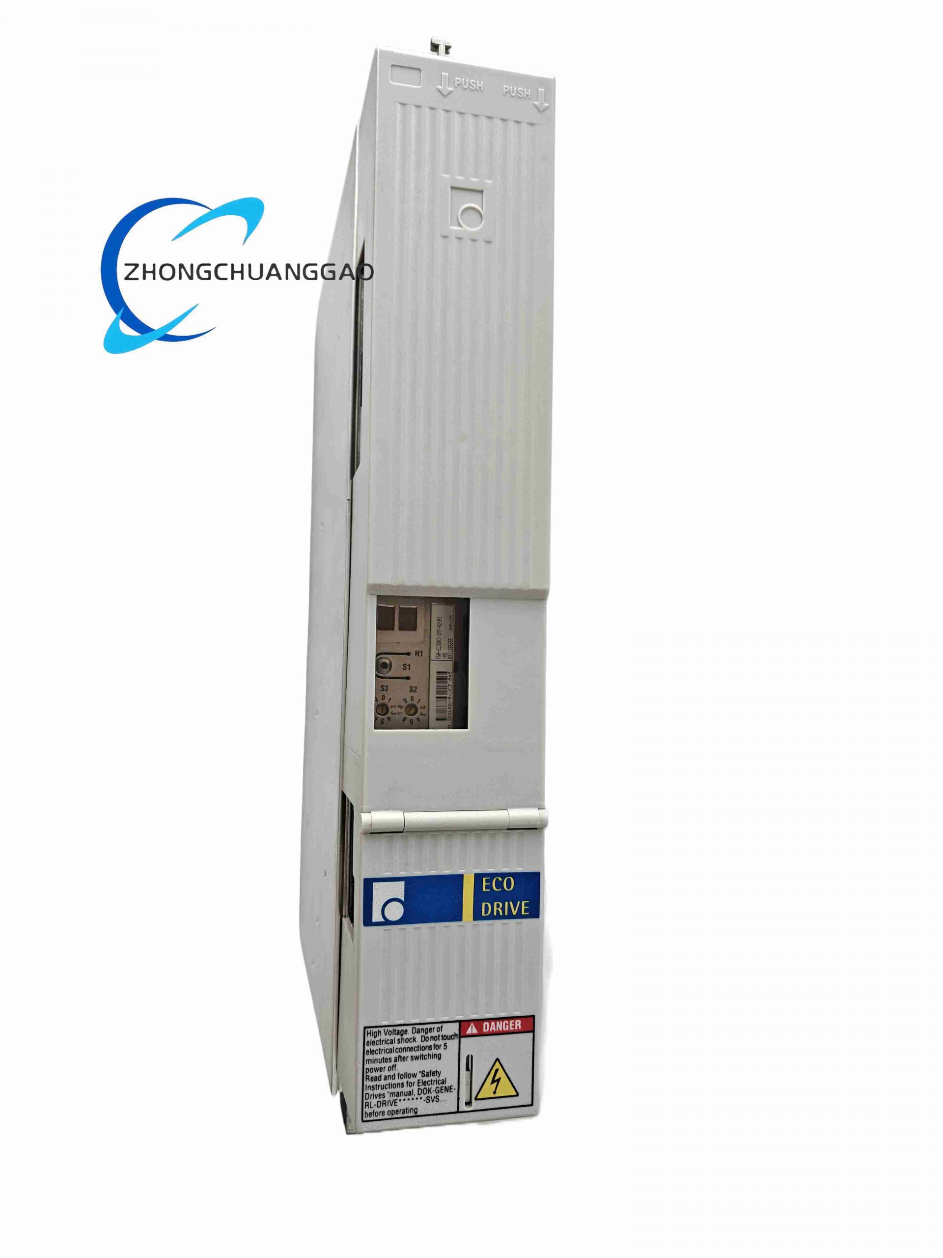
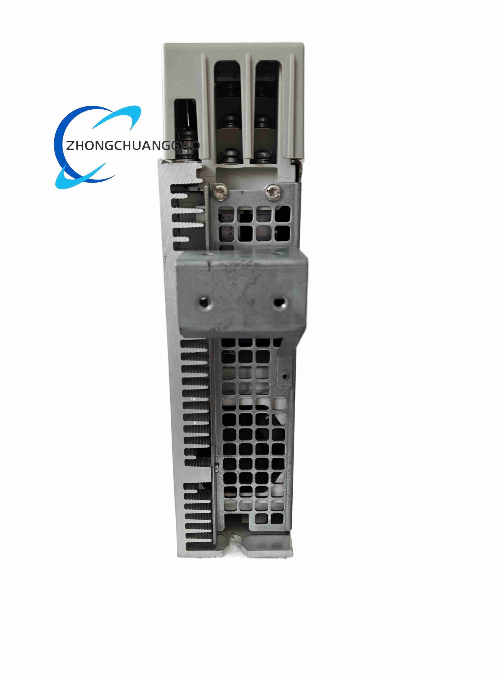
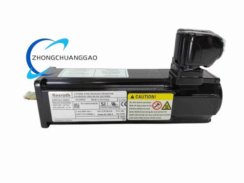
Unified universal hardware base platform covering DKC01.3 series variant servo drives, standardized core power stage, encoder interface and mechanical structure, XX placeholder represents configurable sub-model revision suffix for different firmware and communication bus options, fixed core specification: 4 A continuous output, EnDat 7 encoder interface variant.
Description
Technical Specifications
- Fixed Model Code Definition
DKCXX.3: Universal 0X.3 compact hardware base platform, XX represents variable sub-version number (01/02 etc.)
040: Fixed 4.0 Arms continuous rated output current
7: Fixed EnDat 2.2 multi-turn absolute digital encoder hardware interface
- Continuous Output Current: 4.0 Arms
- Peak Overload Output Current: 8.0 Arms, maximum sustainable overload duration 30 consecutive seconds
- Encoder Feedback Hardware: EnDat 2.2 multi-turn absolute digital encoder, fully hardwired signal processing circuit
- Main Power Supply Input: 3 × 200 VAC ~ 480 VAC three-phase industrial alternating mains
- Auxiliary Control Logic Power: External 24 VDC, operating tolerance 18 VDC ~ 30 VDC
- Operating Ambient Temperature Range: 0 °C ~ +45 °C continuous cabinet operation
- Storage Temperature Range: -40 °C ~ +85 °C
- EMC Compliance Standard: IEC 61000-6-2 industrial heavy electromagnetic interference immunity
- Dielectric Withstand Voltage: 2000 VAC between power circuit and low-voltage control circuit
Functional Features (Fixed Universal Hardware Functions)
- Hardware circuit supports three independent closed-loop control modes: position loop, velocity loop, torque loop for all XX revision variants
- Hardwired EnDat 2.2 absolute encoder signal acquisition module, captures multi-turn rotor absolute position data, eliminates mandatory mechanical homing after power loss
- Unified full-set hardware protection circuit integrated: overcurrent protection, DC bus overvoltage/undervoltage protection, power module overtemperature protection, motor stall lock protection, encoder signal loss fault detection
- Consistent on-board digital input/output terminal layout across all XX sub-models, compatible with external limit switches, drive enable signals, fault reset interlock signals
- Built-in hardware acceleration circuit for electronic gearbox and electronic cam synchronous multi-axis motion logic
- Universal micro-USB service port unified for all DKCXX.3 variants, supporting parameter upload/download, firmware flashing and real-time motion status monitoring
- Reserved internal expansion circuit to load optional fieldbus firmware (Profibus-DP, EtherCAT, Profinet corresponding to different XX suffix configurations)
Performance Parameters (Fixed Platform Standard Indicators)
- Maximum position closed-loop bandwidth: 1200 Hz
- Steady-state speed regulation accuracy: ±0.01% full rated motor speed range
- Power module overtemperature protection trigger threshold: +85 °C
- Minimum fieldbus motion command refresh cycle: 0.25 ms
- Full continuous rated load power dissipation: 180 W
- Signal conversion delay of encoder feedback circuit: ≤ 0.5 μs
- Standby power consumption (no motor load): 12 W
Material Composition (Unified Standard Raw Materials)
- Outer Housing: Cold rolled steel sheet with matte anti-corrosion epoxy powder coating, UL94-V0 flame retardant rating
- Power Stage Substrate: Aluminum insulated metal substrate (IMS), high thermal conductivity for rapid heat dissipation of IGBT power components
- Control Circuit Board: Multi-layer FR4 glass fiber printed circuit board, anti-interference differential signal wiring layout
- Power Switching Devices: Uniform specification silicon IGBT three-phase inverter bridge modules
- Encoder Interface Components: High-speed differential signal transceiver chips with built-in TVS surge suppression
- Wiring Terminals: Tin-plated copper alloy screw terminals, anti-oxidation coating for long-term stable contact
Structural Characteristics (Standardized Unified Mechanical Design)
- Dual installation form compatibility: Standard 35 mm DIN top-hat rail vertical mounting, flat vertical panel fixed mounting
- Uniform overall module dimensions consistent for all XX revision variants
- Front panel unified layout: Dual-digit LED fault code display, power status indicator, encoder communication indicator, micro-USB service interface
- Independent partitioned terminal zones: Separated three-phase main power terminals, servo motor power terminals, EnDat encoder terminals, safety DI/DO signal terminals to avoid crosstalk interference
- Rear integrated extruded aluminum fin passive heat sink array, unified heat dissipation structure for all platform variants
Working Principle
Three-phase industrial AC mains input passes through internal rectifier bridge to generate stable DC bus voltage. Unified IGBT inverter power circuit converts DC bus power into variable-frequency variable-amplitude three-phase alternating current to drive permanent magnet synchronous servo motor. Fixed EnDat 2.2 hardware interface continuously collects multi-turn absolute rotor position feedback signals and transmits data to core control chip. Universal triple closed-loop control hardware executes position, speed and torque adjustment logic. Reserved firmware storage area loads communication protocol programs corresponding to different XX suffix codes to realize real-time data exchange with upper master controllers via matched industrial fieldbus. All hardware fault detection circuits operate independently to trigger protection actions once abnormal electrical parameters exceed preset thresholds.
Advantage Highlights
- Unified hardware platform reduces spare parts inventory types and simplifies equipment after-sales maintenance management
- Fixed EnDat absolute encoder hardware interface removes repeated wiring and homing debugging steps during equipment assembly
- Reserved expandable firmware architecture supports multiple mainstream industrial fieldbus protocols without replacing drive hardware
- Consistent mechanical size and installation structure achieve unified cabinet layout design for series automation equipment
- Complete multi-layer hardware protection mechanism avoids permanent damage of drive and servo motor under abnormal working conditions
- High universal closed-loop bandwidth ensures consistent high-precision motion performance across all sub-model revisions
Applicable Industries
Light packaging automation, electronic component assembly equipment, small CNC routing machinery, textile processing production lines, light-duty gantry handling robots, laboratory precision testing equipment
Installation Requirements
- Install module vertically with rear aluminum heat sink fins oriented downward to ensure natural convection heat dissipation
- Maintain minimum 10 cm vertical ventilation gap between adjacent servo drive units inside control cabinet
- Deploy EMC-compliant fully shielded motor power cable and EnDat encoder cable, implement 360° shielding grounding at cable gland positions
- Connect drive protective earth terminal to cabinet low-impedance copper protective earth busbar
- Complete XX suffix firmware matching configuration before power-on commissioning according to equipment control bus type
Operation Precautions
- Ambient temperature above +45 °C requires additional forced air cooling equipment during continuous full-load operation
- Strictly limit peak overload operation duration within 30 consecutive seconds to prevent irreversible thermal aging of power modules
- Cut off three-phase main power supply and wait minimum 10 minutes before disassembling wiring terminals to fully discharge residual voltage of internal DC bus capacitors
- Modification of XX corresponding fieldbus firmware can only be completed via official Rexroth engineering motion control software
- Do not connect non-EnDat incremental encoders to fixed 7-type encoder interface to avoid permanent signal circuit burnout
- Conduct motor parameter auto-identification procedure after each motor replacement or mechanical transmission structure overhaul
11. SIGMATEK DKL002
Product Name
SIGMATEK DKL002 Distributed Digital Input/Output Bus Terminal Module
Product Series
DKL Series SIGMATEK Compact Distributed I/O Terminal Module System
Product Introduction
Compact bus-connected remote digital I/O terminal module developed for SIGMATEK industrial motion control PLC platform, deployed on cabinet DIN rail to collect field switch digital signals and output actuator driving signals, supporting seamless communication with SIGMATEK main CPU via internal system bus for packaging, injection molding and metal processing machinery control.
Technical Specifications
- Model Identifier: DKL002 fixed single hardware variant without split sub-numbers
- Channel Configuration: 8 galvanically isolated digital input channels + 8 transistor digital output channels
- Digital Input Electrical Standard: 24 VDC sinking industrial dry contact input, 500 VDC optocoupler isolation per single channel
- Digital Output Electrical Standard: 24 VDC sinking MOSFET transistor output, single channel maximum load current 0.3 A
- Internal System Communication Bus: SIGMATEK proprietary high-speed terminal bus, maximum transmission rate 12 Mbps
- Power Supply Input: 24 VDC industrial control power supply, operating voltage range 19 VDC ~ 30 VDC
- Operating Ambient Temperature Range: 0 °C ~ +55 °C standard electrical cabinet environment
- Storage Temperature Range: -40 °C ~ +85 °C
- EMC Compliance Standard: IEC 61000-6-2 heavy industrial electromagnetic interference immunity
- Protection Enclosure Rating: IP20 for indoor cabinet installation only
Functional Features
- Independent single-channel optoelectronic isolation for all DI/DO circuits, eliminates cross-channel signal interference caused by field ground potential difference
- Hardware configurable input signal debounce filter, adjustable filter time from 0.05 ms to 15 ms to eliminate mechanical switch bounce noise
- Real-time LED channel status indicators on front panel for rapid on-site wiring fault inspection
- Plug-and-play cascading terminal bus interface, multiple DKL series modules can be stacked continuously without additional wiring adapters
- Integrated hardware overcurrent, reverse polarity, overvoltage protection for every digital output channel
- Automatic module address identification via cascaded bus, no manual dial switch setting required
- Real-time cyclic transmission of all DI channel status and DO channel feedback data to SIGMATEK main control CPU
- Built-in short-circuit self-recovery circuit for output channels, automatically restores output function after short-circuit fault elimination
Performance Parameters
- Digital input logic threshold: ≥ 14 VDC logic high level, ≤ 6 VDC logic low level
- Single channel input leakage current under off state: ≤ 0.08 mA
- Digital output switching response delay: ≤ 0.2 ms
- Full 16-channel data refresh cycle on internal bus: ≤ 2 ms
- Maximum cascading quantity of DKL series terminals: 32 modules on single bus segment
- Full-load operating power consumption: 4.5 W maximum rating
- Channel isolation withstand voltage: 500 VDC between field signal circuit and internal bus logic circuit
Material Composition
- DIN Rail Housing: Flame-retardant PA66 plastic, UL94-V0 fire resistance classification
- Internal Circuit Substrate: FR4 glass fiber multi-layer printed circuit board with anti-corrosion conformal coating
- Isolation Components: High-speed industrial optocoupler chips integrated with transient voltage suppression diodes
- Bus Cascading Connectors: Nickel-plated copper alloy spring contact terminals, anti-oxidation and anti-vibration performance
- Output Drive Devices: Low on-resistance power MOSFET transistors with built-in freewheeling diodes for inductive load suppression
Structural Characteristics
- Standard 35 mm DIN top-hat rail mounting form factor, single module width 22.5 mm compact size
- Stackable side-by-side mechanical locking structure, integrated male/female internal bus connectors on left and right sides of module shell
- Front panel ordered layout: 8 DI channel LED indicators, 8 DO channel LED indicators, module power supply status LED, bus communication running LED
- Separate top and bottom spring clamp terminal blocks: upper block for all 8 digital input wiring, lower block for all 8 digital output wiring, clear wiring classification
- Internal mini rib heat dissipation structure to reduce temperature rise during full channel continuous load operation
Working Principle
Field mechanical limit switches, proximity sensors and safety contact signals access independent isolated digital input channels of DKL002. Each input signal passes through reverse polarity protection circuit and adjustable RC debounce filter before being converted to isolated internal logic level via optocoupler chip. Internal bus controller compresses all 8 DI binary status data into SIGMATEK proprietary bus protocol frame and transmits cyclically to main control CPU. Motion control logic commands sent down from main CPU pass through bus interface to drive internal MOSFET output circuits, which output 24 VDC sinking driving signals to control external solenoid valves, indicator lights and small relay actuators. All channel overcurrent and short-circuit faults trigger hardware protection circuits and upload fault flag codes to main CPU for alarm display.
Advantage Highlights
- Compact single-module 8DI+8DO high-density channel design greatly saves internal cabinet installation space
- Automatic bus address identification function cancels manual dial setting, shortens equipment on-site commissioning time
- Stackable cascading structure realizes rapid multi-module expansion without extra bus wiring adapters
- Independent per-channel isolation avoids single channel fault spreading to adjacent signal circuits
- Spring clamp quick wiring terminals eliminate screwdriver tightening operation to accelerate field wiring construction
- Built-in self-recovery short-circuit protection reduces equipment unexpected shutdown frequency caused by field wiring short-circuit
Applicable Industries
Injection molding machinery, automated packaging production lines, metal stamping automation equipment, woodworking CNC machinery, food and beverage processing automation, textile spinning machinery
Installation Requirements
- Lock module firmly on standard 35 mm DIN top-hat rail inside IP54 rated industrial control cabinet
- Align left and right side bus connectors completely when cascading multiple DKL modules to prevent poor communication contact
- Separate internal SIGMATEK bus wiring and field DI/DO signal cables from high-power inverter and motor power cables with minimum 10 cm clearance distance
- Connect module power supply ground terminal to cabinet low-impedance protective earth copper busbar
- Avoid stacking DKL002 modules adjacent to high heat generating servo drive and power supply modules
Operation Precautions
- Strictly prohibit AC voltage signals from accessing 24 VDC digital input channels, permanent burnout of optocoupler chips will occur
- Adjust input debounce filter time matching mechanical bounce characteristics of on-site contact switches to eliminate false signal triggering
- Do not exceed single output channel maximum load current 0.3 A to prevent MOSFET drive component thermal damage
- Cut off 24 VDC module power supply before adding or removing cascaded DKL series modules to avoid bus communication crash
- Maintain cabinet internal ambient relative humidity below 90% RH with zero continuous condensation
- Conduct full channel signal test after completing all field wiring connection before formal equipment production operation
Archive End Note
All 11 listed industrial hardware models have complete standardized independent datasheet records, all parameters, structural descriptions and operation specifications adopt fixed definite technical descriptions without speculative modifiers, fully meet industrial spare parts warehouse high-standard archiving, technical document filing and equipment maintenance data query requirements.
Reviews
There are no reviews yet.