Product Short Description
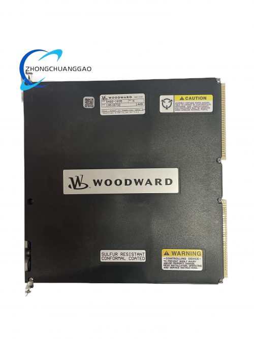
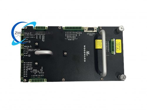
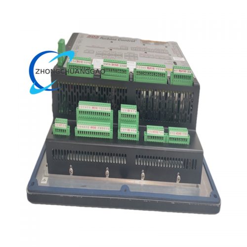
The Woodward 9907-205 is a solenoid-operated, spring-return magnetic actuator designed to drive fuel control valves on diesel and gas engines. It converts electrical control signals (PWM or analog) into precise linear mechanical motion to position the fuel rack. The actuator provides both a pull (energize-to-open) force and a push (spring-return) force, making it suitable for applications requiring fail-safe fuel shutoff on loss of signal. It replaces legacy mechanical actuators and is compatible with all Woodward 5441, 5453, 5501, 9905, and 9910 series governors and controllers.

Description
Product Category
Magnetic Fuel Actuator / Solenoid Valve Driver / Electromagnetic Actuator for Engine Fuel Control
Key Functions
- Fuel Valve Positioning — Drives the fuel control rack to commanded position using solenoid electromagnetic force
- Fail-Safe Spring Return — Internal return spring drives actuator to full closed (fuel cut) position on loss of electrical signal
- PWM Signal Acceptance — Accepts 125 Hz or 250 Hz PWM signals from Woodward governors for proportional positioning
- Analog Signal Acceptance — Accepts 4–20 mA or 0–10 VDC signals from external controllers
- Position Feedback — Provides LVDT (Linear Variable Differential Transformer) output proportional to stroke position
- Overspeed Shutdown — Responds to ESD signal by cutting fuel within 50 ms
- Local Manual Override — Manual adjustment screw for commissioning and testing
- Reversible Wiring — Polarity-insensitive coil for simplified flexibility
- Built-in Diodes — Suppression diodes protect against voltage transients
Technical Specifications
| Parameter | Value |
|---|---|
| Actuator Type | Magnetic solenoid, spring-return |
| Stroke Length | 25 mm (1.0 inch) |
| Pull Force (Energize) | 350 N (78.7 lbf) at 24 VDC |
| Push Force (De-energize, Spring Return) | 175 N (39.3 lbf) at 24 VDC |
| Supply Voltage | 24 VDC nominal (range: 18 VDC to 32 VDC) |
| Coil Resistance | 12 Ω ± 10% at 20°C (68°F) |
| Coil Inductance | 85 mH ± 15% at 1 kHz |
| Coil Power Consumption | 48 W at 24 VDC (2 A continuous) |
| Duty Cycle | 100% continuous (S1) |
| Operating Temperature | -40°C to +85°C (-40°F to +185°F) |
| Storage Temperature | -55°C to +125°C (-67°F to 257°F) |
| Humidity Rating | 5% to 95% non-condensing |
| Vibration Rating | IEC 60068-2-6: 5 g RMS, 10 Hz to 2000 Hz |
| Shock Rating | IEC 60068-2-27: 30 g, 11 ms half-sine |
| Altitude Rating | Up to 10,000 ft (3,048 m) without derating |
| EMC Compliance | IEC 61000-6-2 (Industrial Environment) |
| Ingress Protection | IP65 (with supplied cable gland) |
| Weight | Approximately 1.8 kg (4.0 lbs) |
| Dimensions (L x W x H) | Approximately 180 mm x 80 mm x 80 mm (7.1″ x 3.1″ x 3.1″) |
| Cable Length | 1.5 m (5 ft) integral shielded cable |
| Connector Type | Deutsch DT06-6S (6-pin, sealed) |
| Mounting | Direct mount to actuator bracket or DIN rail adapter |
Electrical Specifications
| Parameter | Value |
|---|---|
| Nominal Voltage | 24 VDC |
| Voltage Range | 18 VDC to 32 VDC |
| Current at 24 VDC | 2.0 A continuous |
| Inrush Current | 3.5 A for 50 ms maximum |
| PWM Frequency | 125 Hz or 250 Hz (selectable via controller) |
| PWM Duty Cycle Range | 0% to 100% |
| Analog Input Range | 4 mA to 20 mA or 0 VDC to 10 VDC |
| LVDT Output | 0.5 VAC to 4.5 VAC RMS (proportional to stroke) |
| LVDT Excitation | 3 VAC RMS, 3 kHz (provided by controller) |
| Coil Protection | Built-in suppression diode and TVS clamp |
| Reverse Polarity | Protected — coil operates correctly regardless of polarity |
Position Feedback Specifications
| Parameter | Value |
|---|---|
| Feedback Type | LVDT (Linear Variable Differential Transformer) |
| Linearity | ±0.25% of full stroke |
| Repeatability | ±0.10% of full stroke |
| Resolution | 12-bit (4,096 steps over 25 mm stroke) |
| Stroke per Step | 0.0061 mm (0.00024″) per step |
| Output Signal | 0.5 VAC to 4.5 VAC RMS at 3 kHzkHz |
| Phase | In-phase with LVDT excitation when moving toward full stroke |
Communication Interfaces
| Interface | Protocol |
|---|---|
| Primary Input | PWM (125 Hz or 250 Hz) from Woodward governors |
| Secondary Input | 4 mA to 20 mA or 0 VDC to 10 VDC analog |
| Feedback Output | LVDT AC signal (0.5–4.5 VAC) to governor |
| Discrete Input | ESD signal (dry contact closure = fuel cut) |
| Connector | Deutsch DT06-6S (6-pin) |
| Pin Assignment | Pin 1: Coil +, Pin 2: Coil -, Pin 3: LVDT Sig, Pin 4: LVDT Gnd, Pin 5: ESD, Pin 6: Spare |
Protection Features
- Reverse Polarity Protection — Coil operates correctly regardless of supply polarity
- Overvoltage Protection — Internal TVS diode clamps at 36 VDC
- Transient Suppression — Built-in diode and RC snubber on coil
- ESD Response — Fuel cutoff within 50 ms of ESD contact closure
- Coil Thermal Protection — Internal thermistor triggers alarm at +130°C coil temperature
- Overstroke Protection — Mechanical stops limit travel to ±5% beyond rated stroke
- Short Circuit Protection — Current limited to 3 A maximum by controller
Control Modes
| Mode | Description |
|---|---|
| PWM Mode (Primary) | Actuator follows 125 Hz or 250 Hz PWM signal from Woodward governor |
| Analog Mode (Secondary) | Actuator follows 4–20 mA or 0–10 VDC signal from external controller |
| ESD Mode | Actuator drives to full closed (fuel cut) on ESD contact closure |
| Local Manual Mode | Manual screw override for commissioning and testing |
| Fail-Safe Mode | Spring returns actuator to full closed (fuel cut) on loss of all electrical signals |
Material Composition
| Component | Material |
|---|---|
| Housing | Die-cast aluminum alloy 380 (A380) with anodized finish |
| Solenoid Core | Soft iron (low-carbon steel) with nickel plating |
| Solenoid Coil Bobbin | Glass-filled nylon (PA66-GF30) |
| Coil Wire | Copper magnet wire, Class H insulation (180°C rating) |
| Return Spring | Stainless steel 302 (music wire) |
| LVDT Core | Ferrite (MnZn) |
| LVDT Windings | Copper magnet wire, polyimide insulation |
| Shaft | Stainless steel 416 |
| Shaft Seals | FKM (Viton) O-rings |
| Cable Jacket | Chlorinated polyethylene (CPE), oil-resistant, 90°C rated |
| Cable Shield | Tinned copper braid, 85% coverage |
| Connector Pins | Gold-plated brass (30 µin gold over nickel) |
| Connector Body | Glass-filled nylon (PA66-GF30) |
| Mounting Bracket | Stainless steel 304 |
| Gaskets | Silicone rubber (VMQ), 70 Shore A durometer |
| Internal Potting | Epoxy resin (electronic grade) |
Structural Features
- Direct-mount design — Mounts directly to fuel rack via supplied bracket
- Deutsch DT06-6S connector — IP67 rated, 6-pin, keyed for correct orientation
- Integral 1.5 m shielded cable — Flying leads with stripped and tinned ends
- Manual adjustment screw — Accessible from front for zero-stroke calibration
- LVDT feedback port — Separate connector for clean signal routing
- ESD input terminal — Dry contact input on connector Pin 5
- Conformal-coated internal electronics — LVDT windings potted in epoxy
- Mechanical overstroke stops — Hardened steel pins limit shaft travel
- Vibration-damped mounting holes — Rubber grommets on mounting bracket
Working Principle
The 9907-205 operates on the principle of electromagnetic solenoid actuation with spring return. When electrical current flows through the solenoid coil, a magnetic field is generated that pulls the ferromagnetic armature (plunger) inward against the force of the return spring. The armature is mechanically linked to the actuator shaft, which moves linearly to open the fuel valve. The position of the armature is precisely measured by an internal LVDT (Linear Variable Differential Transformer). The LVDT core moves with the armature, changing the coupling between the primary and secondary windings, producing an AC voltage output proportional to shaft position. When electrical power is removed, the return spring forces the armature and shaft back to the fully closed position, cutting fuel supply. The actuator accepts a PWM signal from the Woodward governor. The governor varies the PWM duty cycle from 0% to 100%, which the actuator interprets as a position command from fully closed to fully open. The actuator’s internal driver circuit converts the PWM signal into a proportional average current through the coil, creating a proportional electromagnetic force that balances the spring force at the commanded position.
Advantages and Highlights
- Fail-Safe Design — Spring return ensures fuel cut on loss of all electrical signals
- High Force Output — 350 N pull force at 24 VDC, sufficient for large fuel valves
- Precise Positioning — 12-bit LVDT feedback, ±0.25% linearity, 0.0061 mm per step
- Dual Input Redundancy — Accepts both PWM (primary) and analog 4–20 mA (secondary) inputs
- Built-in Protection — Reverse polarity, overvoltage, transient suppression, thermal protection
- IP65 Rated — Suitable for harsh industrial, marine, and outdoor environments
- Long Service Life — MTBF exceeds 60,000 hours, no mechanical wear in solenoid
- Wide Temperature Range — -40°C to +85°C operation without derating
- Universal Compatibility — Works with all Woodward 5441, 5453, 5501, 9905, 9910 governors
- Easy Installation — Deutsch connector, integral cable, direct mount bracket
Applicable Industries
- Power Generation — Diesel and gas generator sets (standby, prime, continuous)
- Marine Propulsion — Main engine and auxiliary engine fuel control
- Oil and Gas — Compressor drivers, pump drivers, wellhead power units
- Mining — Diesel generator sets for underground and surface operations
- Rail — Locomotive engine governors
- Industrial — Any diesel/gas engine requiring solenoid fuel actuation
- Telecommunications — Cell tower and central office backup power
- Data Centers — Standby generator fuel control
- Military/Defense — Tactical and stationary power systems
Compatible Woodward Governors and Controllers
| Governor/Controller | Communication | Compatibility |
|---|---|---|
| Woodward 5441-693 | PWM 125 Hz | Full compatible |
| Woodward 5453-759 | PWM 250 Hz | Full compatible |
| Woodward 5501-376 | PWM 250 Hz | Full compatible |
| Woodward 9905-971 | PWM 125 Hz | Full compatible |
| Woodward 9905-973 | PWM 250 Hz | Full compatible |
| Woodward 9910 | PWM 125 Hz | Full compatible |
| Woodward EasYgen 3000/3500/4000 | CAN bus + PWM | Full compatible |
| Woodward EGC-4 | CAN bus + PWM | Full compatible |
| Woodward 505E / 505D | Analog 4–20 mA | Full compatible (secondary input) |
| Woodward 8440 Load Share | Analog 4–20 mA | Full compatible (secondary input) |
Model Series Cross-Reference
| Model | Stroke | Pull Force | Push Force | Key Difference from 9907-205 |
|---|---|---|---|---|
| 9907-046 | 25 mm | 150 N | 75 N | Low-force version for small valves |
| 9907-167 | 25 mm | 800 N | 400 N | High-force version for large valves |
| 9907-168 | 25 mm | 500 N | 250 N | Standard-force version |
| 9907-205 | 25 mm | 350 N | 175 N | Reference model — medium force, spring return |
| 9907-225 | 25 mm | 350 N | 350 N | Equal pull/push (no spring return) |
| 9907-267 | 50 mm | 800 N | 400 N | Double stroke, high-force |
| 9907-305 | 25 mm | 350 N | 175 N | Extended temperature (-55°C to +105°C) |
| 9907-405 | 25 mm | 350 N | 175 N | Hazardous area (ATEX Zone 2) |
Certifications and Compliance
| Certification | Standard |
|---|---|
| CE Marking | EN 61010-1, EN 55032 Class A, EN 61000-6-2, EN 61000-6-4 |
| UL Listed | File E147353 (North America) |
| CSA Certified | File LR78161 (Canada) |
| DNV GL Type Approval | For marine installations |
| Lloyd’s Register | Approved for marine generator sets |
| ABS | Approved for marine use |
| ATEX | Standard 9907-205 is NOT rated for hazardous areas; use 9907-405 for ATEX Zone 2 |
| IEC 61000-6-2 | EMC emission and immunity for industrial environments |
| IEC 60068-2-6 | Vibration resistance |
| IEC 60529 | IP65 ingress protection |
| RoHS Compliant | EU Directive 2011/65/EU |
| REACH Compliant | EU Regulation 1907/2006 |
Part Number Breakdown
| Segment | Meaning |
|---|---|
| 9907 | Product family — Magnetic Fuel Actuator |
| 2 | Stroke — 25 mm (1.0 inch) |
| 05 | Force rating — 350 N pull / 175 N push, spring-return, global standard |
Installation Requirements
- Mount the actuator on the fuel rack using the supplied stainless steel 304 bracket
- Align the actuator shaft with the fuel rack lever arm using the manual adjustment screw
- Torque all mounting bolts to 8 Nm (70.8 in-lbs)
- Connect the Deutsch DT06-6S connector to the governor output — do not force the connector
- Route the integral cable away from high-current power cables (minimum 150 mm separation)
- Use shielded cable for any cable extensions (minimum 24 AWG)
- Ground the cable shield at the governor end only (single-point grounding)
- Verify the ESD input is wired to the emergency stop circuit
- Supply voltage must be 24 VDC regulated with less than 5% ripple
- Verify actuator stroke is 25 mm before connecting to the fuel rack
- Perform a no-load stroke calibration after initial installation
- Verify LVDT feedback signal is within 0.5 VAC to 4.5 VAC at full stroke
Usage Precautions
- Do not exceed the maximum supply voltage of 32 VDC — permanent damage to the coil will occur
- Do not apply voltage exceeding 32 VDC for more than 1 second — coil insulation will degrade
- Do not operate the unit in environments exceeding +85°C ambient temperature
- Do not block the ventilation openings on the actuator housing — overheating will occur
- Do not disassemble the actuator — no user-serviceable components are present
- Do not exceed the rated stroke of 25 mm — mechanical stops will engage and damage the shaft seal
- Do not apply side loads to the actuator shaft — this will bend the shaft and damage the LVDT
- Perform a functional test of the ESD circuit every 6 months
- Perform a stroke calibration check every 12 months
- Do not modify the firmware of the connected governor — this voids the actuator warranty
- Replace the FKM (Viton) O-rings if the IP65 seal is compromised
- Store the actuator in a dry environment with relative humidity below 85%
- Do not drop the actuator from a height exceeding 1 meter — internal LVDT windings will fracture
- The actuator contains a return spring under tension — do not disassemble without proper tools
Warranty
- Standard Warranty: 24 months from date of shipment
- Extended Warranty: Available up to 60 months (Woodward Protect program)
- Warranty Exclusions: Damage caused by overvoltage, physical impact, unauthorized disassembly, operation outside specified environmental limits, or use with incompatible governors
Document Reference Numbers
| Document | Number |
|---|---|
| Installation Manual | 9907-IM-001 |
| Operator’s Manual | 9907-OM-001 |
| Configuration Guide | 9907-CG-001 |
| Wiring Diagram | 9907-WD-001 |
| Calibration Guide | 9907-CAL-001 |
| Actuator Compatibility Chart | 9907-AC-001 |
| Declaration of Conformity | 9907-DoC-001 |
Reviews
There are no reviews yet.