
Product Short Description
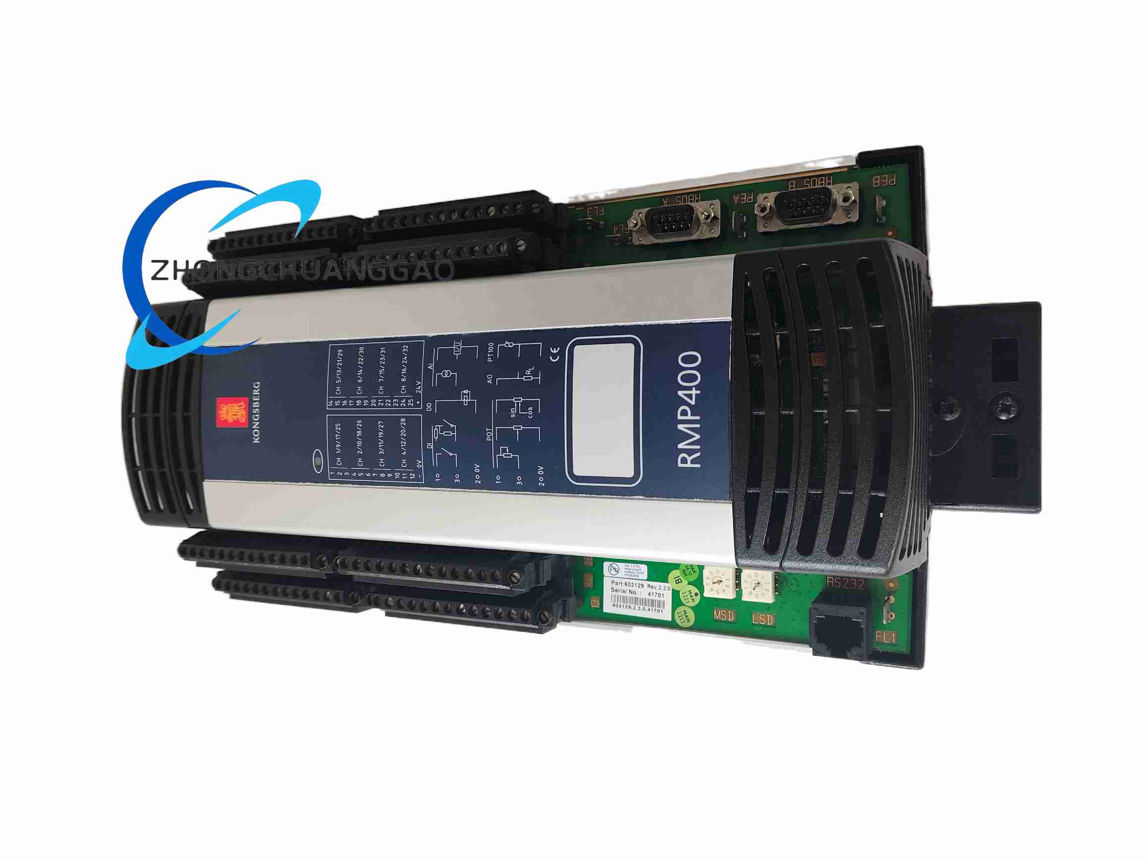
Full Product Name: Kongsberg RMP400 Distributed Remote Multipurpose Control Module, Part Code 603129
This module is a core distributed I/O control unit developed by Kongsberg Maritime for marine ship automation, offshore platform monitoring and industrial process control systems. It acts as a field-side distributed signal acquisition and control execution node, responsible for collecting analog/digital field sensor signals and outputting control commands to field actuators, communicating with the central ship automation control unit via redundant RBUS field bus, realizing decentralized distributed control architecture for marine automation systems.
Description
Core Function Features
- Mixed Analog & Digital Signal Processing: Supports simultaneous acquisition of analog voltage/current signals and digital switch signals, configurable channel types via system software.
- Redundant RBUS Communication Bus: Dual-channel galvanically isolated RS485 RBUS bus, automatic bus switching upon single channel failure to ensure uninterrupted data transmission.
- Full Electrical Channel Isolation: Each I/O channel adopts independent optocoupler isolation circuit, effectively suppressing marine electrical interference such as generator harmonic noise and high-power equipment electromagnetic radiation.
- DIN Rail Modular Hot-Swap Design: Standard 35mm DIN rail snap-on installation, supports hot plugging and replacement without shutting down the entire automation system, minimizing ship equipment maintenance downtime.
- On-Board Channel Status LED Indicators: Independent LED status light for each input/output channel, visual display of channel signal presence, fault, short-circuit or open-circuit state for rapid on-site troubleshooting.
- Marine-Grade Harsh Environment Adaptation: Complies with IEC 60945 marine equipment environmental standards, strong resistance to vibration, salt mist, temperature cycling and high humidity cabin environments.
- Multi-Level Overcurrent & Short-Circuit Protection: Built-in hardware fuse and software overcurrent threshold protection for each I/O channel, automatically cut off faulty channel without affecting normal operation of other channels.
Complete Technical & Performance Parameters
Electrical Power Supply Parameters
- Nominal Operating Input Voltage: 24 VDC
- Allowable Input Voltage Operating Range: 18 VDC ~ 31.2 VDC
- Typical Module Total Power Consumption: 10 W
- Maximum Inrush Current At Power-On: 1.2 A
RBUS Communication Bus Parameters
- Bus Interface Type: Dual redundant 9-pin male D-Sub RS485 connectors
- Galvanic Isolation Voltage Between Bus And I/O Circuits: 1500 VAC for 1 minute
- Supported Communication Baud Rate Range: 300 bps ~ 115200 bps
- Maximum Allowable RBUS Bus Cable Length: 100 meters
- Cable Capacitance Requirement: ≤50 pF per meter
I/O Channel Electrical Specifications
- Analog Signal Input Support: 0–10 VDC voltage signal, 4–20 mA standard industrial current loop signal
- Digital Signal Input Support: NPN/PNP transistor level signals, Namur standard proximity switch signals, dry contact switch signals
- Digital Output Load Capacity: Maximum 0.5 A per channel at 24 VDC load voltage
- Channel Open/Short Circuit Detection Threshold: Digital input channel off-state current <0.5 mA, on-state trigger current >3 mA
Environmental Adaptation Parameters
- Continuous Operating Temperature Range: -20°C ~ +60°C
- Component Storage Temperature Range: -40°C ~ +70°C
- Relative Humidity Operating Range: 5% ~ 95% non-condensing
- Vibration Resistance Standard: IEC 60068-2-6, continuous vibration 0.7 g acceleration
- Protection Enclosure Grade: IP20 (indoor control cabinet installation only)
Mechanical Dimensions & Weight
- Overall Module Size: 130 mm height × 130 mm depth × 35 mm width
- Net Module Weight: 0.34 kg
Material Composition & Structural Features
Material Composition
- Outer Module Housing: Flame-retardant black reinforced polycarbonate plastic, UL94-V0 fire resistance rating, salt mist corrosion resistant, high impact resistance to mechanical collision during ship maintenance.
- Internal Circuit Substrate: High TG glass fiber epoxy PCB board, marine-grade anti-humidity coating to prevent PCB circuit corrosion under high salt mist cabin conditions.
- Terminal Connection Blocks: Copper alloy gold-plated screw terminals, anti-oxidation, low contact resistance under long-term vibration working conditions.
- DIN Rail Snap-On Buckle: Glass fiber reinforced nylon plastic, high mechanical fatigue resistance for repeated module disassembly and replacement.
- Internal Isolation Components: High linearity optocoupler chips, high withstand voltage ceramic isolation capacitors for channel signal isolation.
Structural Features
- Vertical layered internal circuit layout: Power supply circuit layer, RBUS communication circuit layer, analog/digital I/O channel circuit layer are independently separated to minimize cross-channel electrical interference.
- Dual redundant D-Sub RBUS communication connectors mounted on module right side, clear marking of RBUS A and RBUS B redundant channels for wiring identification.
- Top and bottom multi-row screw terminal block layout, independent wiring terminals for power supply, analog input, digital input, digital output channels, each terminal printed with channel number marking to avoid wiring confusion.
- Integrated horizontal heat dissipation grille on module front panel, natural convection heat dissipation design without built-in cooling fans, eliminating fan failure risk in unattended marine cabin control cabinets.
- Standard dual 35mm DIN rail mounting buckle structure, module can be quickly installed or removed from DIN rail by pressing the plastic buckle without additional disassembly tools.
Working Principle
- Power Supply Circuit Regulation: The 24VDC ship control power input passes through an EMI filter circuit, overvoltage and reverse connection protection circuit, then is converted into multiple groups of stable isolated low-voltage DC power supplies to supply power to the RBUS communication chip, analog signal acquisition circuit, digital logic processing unit and channel drive circuits respectively.
- Field Signal Acquisition Process:
- Analog sensor signals (4–20mA pressure/temperature transmitters, 0–10V level sensors) enter the analog input channel, pass through low-pass anti-aliasing filter circuits, then are converted into digital numerical values by high-resolution A/D conversion chips, buffered and stored in the module local memory.
- Digital switch signals (limit switches, door contact switches, Namur flame detection switches) pass through optocoupler isolation circuits to eliminate ground loop interference, the logic level signal is captured by the module built-in microcontroller, and channel on/off state data is stored.
- Redundant RBUS Data Transmission & Central Control Interaction: The module microcontroller packs all collected analog and digital signal data into standard Kongsberg RBUS communication data frames, then transmits the data frame to the ship central automation control unit through RBUS A main bus channel. If the main RBUS A channel suffers cable breakage or communication failure, the module hardware detection circuit automatically switches data transmission to the standby RBUS B redundant channel without data loss or system interruption.
- Control Command Output Execution Process: The central control unit sends digital output switch control commands or analog output regulation commands via the RBUS bus to the RMP400 module. The module microcontroller parses the received control commands, drives the corresponding digital output channel transistor switch or analog output D/A conversion circuit, outputs 24VDC switch signals or 4–20mA regulation signals to control field actuators including solenoid valves, alarm buzzers, proportional regulating valves and relay contactors.
- Channel Fault Self-Diagnosis Mechanism: The module internal microcontroller continuously scans each I/O channel in real time, detecting abnormal electrical states including channel short-circuit, wire open-circuit, overcurrent load and abnormal analog signal out-of-range values. Once a channel fault is detected, the module immediately locks the faulty channel output, lights the corresponding channel fault LED indicator, and uploads fault code information to the central control system via RBUS bus for operator alarm notification and fault positioning.
Application Scenarios
- Marine cargo ship main engine automation monitoring systems: Collect main engine cylinder temperature, lubricating oil pressure, cooling water level analog signals, output control signals to main engine auxiliary solenoid valves and alarm equipment.
- Offshore oil & gas platform safety monitoring and control systems: Process platform fire smoke detector digital switch signals, gas concentration analog transmitter signals, output emergency shutdown valve control signals for platform process pipelines.
- Ship ballast tank liquid level monitoring control systems: Collect ballast tank liquid level 4–20mA transmitter signals, output control signals to ballast water inlet/outlet solenoid valves, realize automatic ballast tank liquid level regulation.
- Ship auxiliary machinery control cabinets (fresh water generator, sewage treatment unit, air compressor): Distributed signal acquisition and local actuator control for auxiliary equipment operation parameters and status signals.
- Coastal industrial factory marine water treatment process control systems: On-site distributed node signal collection and valve actuator control for seawater desalination and industrial wastewater treatment processes.
Installation Requirements
- Control Cabinet DIN Rail Installation: Mount standard 35mm width DIN rail horizontally inside the IP54 marine control cabinet, align the RMP400 module upper and lower plastic buckles with the DIN rail, press the module firmly downward until the buckle clicks to lock onto the DIN rail; ensure at least 10mm vertical heat dissipation gap between adjacent installed modules to avoid heat accumulation.
- Power Supply Wiring Installation: Connect ship standard 24VDC isolated control power supply to the dedicated power input screw terminals of the module, strictly distinguish positive and negative power polarities; use stranded copper control cables with cross-sectional area of 0.75mm² ~ 2.5mm², terminal screw tightening torque controlled at 0.4 Nm ~ 0.5 Nm to prevent loose wiring under ship vibration conditions.
- RBUS Redundant Bus Wiring Installation: Use shielded twisted pair RS485 bus cables for RBUS A and RBUS B redundant channel wiring, connect cable shield layer single-ended grounding at the central control cabinet end only, prohibit double-ended grounding to avoid ground loop interference; RBUS bus cable laying path must be separated at least 30cm away from ship high-power AC power cables to prevent electromagnetic signal interference.
- Field I/O Sensor & Actuator Wiring Installation: Separate analog signal sensor cables and digital switch signal cables into independent wiring wire ducts inside the control cabinet to avoid analog signal noise interference from digital switching pulses; each field wiring terminal must be marked with unique cable identification tags corresponding to the ship automation system wiring drawing for maintenance traceability.
- Environmental Installation Limitation: The RMP400 module is only allowed to be installed inside closed marine control cabinets with IP54 or higher enclosure protection grade, prohibited from direct installation in open deck exposed environments with direct sea water splash and heavy salt mist exposure; for tropical high-temperature ship cabin control cabinets, install auxiliary cabinet ventilation fans to maintain cabinet internal operating temperature below +60°C.
Operation & Maintenance Precautions
- Power-On Commissioning Precautions: Before supplying 24VDC power to the module, use a multimeter to check all wiring terminals for short-circuit between positive and negative power lines and between signal wiring terminals; confirm no wiring misconnection before closing the control cabinet power circuit breaker to avoid module internal circuit burnout due to short-circuit faults.
- Hot-Swap Module Replacement Precautions: When replacing a faulty RMP400 module during system online operation, do not disconnect the RBUS bus wiring first; press the module lower DIN rail release buckle to detach the faulty module from the DIN rail, quickly install the new spare module onto the DIN rail, re-connect the RBUS bus connectors and field I/O wiring terminals in original order; after replacement completes, access the central control system configuration software to verify all channel signal data and control output functions operate normally.
- Daily Routine Maintenance Precautions: Every weekly ship equipment inspection cycle, visually check all module front panel channel LED indicators for abnormal fault light illumination; use compressed dry nitrogen low-pressure air gun (air pressure not exceeding 0.2 MPa) to blow off accumulated dust on the module heat dissipation grille and terminal block wiring area, prohibit using liquid cleaning solvents to wipe the module circuit components and plastic housing to avoid chemical corrosion damage.
- Long-Term Storage Precautions: Spare unused RMP400 modules must be sealed and stored in a constant temperature and humidity storage warehouse with temperature controlled at 10°C ~ 25°C and relative humidity 40% ~ 60%, with desiccant moisture absorption bags placed inside storage packaging to prevent PCB circuit board damp corrosion; storage packaging must be sealed with anti-static shielding bags to avoid static electricity damaging internal electronic chips during transportation and storage.
- Fault Troubleshooting Precautions: If the module cannot communicate with the central control unit via RBUS bus, first inspect the RBUS A and B bus wiring connectors for loose pins or damaged cable shielding layers; if individual I/O channels continuously report open-circuit or short-circuit fault alarms, first disconnect the field external sensor/actuator wiring to eliminate external field equipment faults, do not disassemble the module internal housing without professional Kongsberg marine automation maintenance technicians, unauthorized disassembly will invalidate the product marine equipment certification and warranty service.
Reviews
There are no reviews yet.