
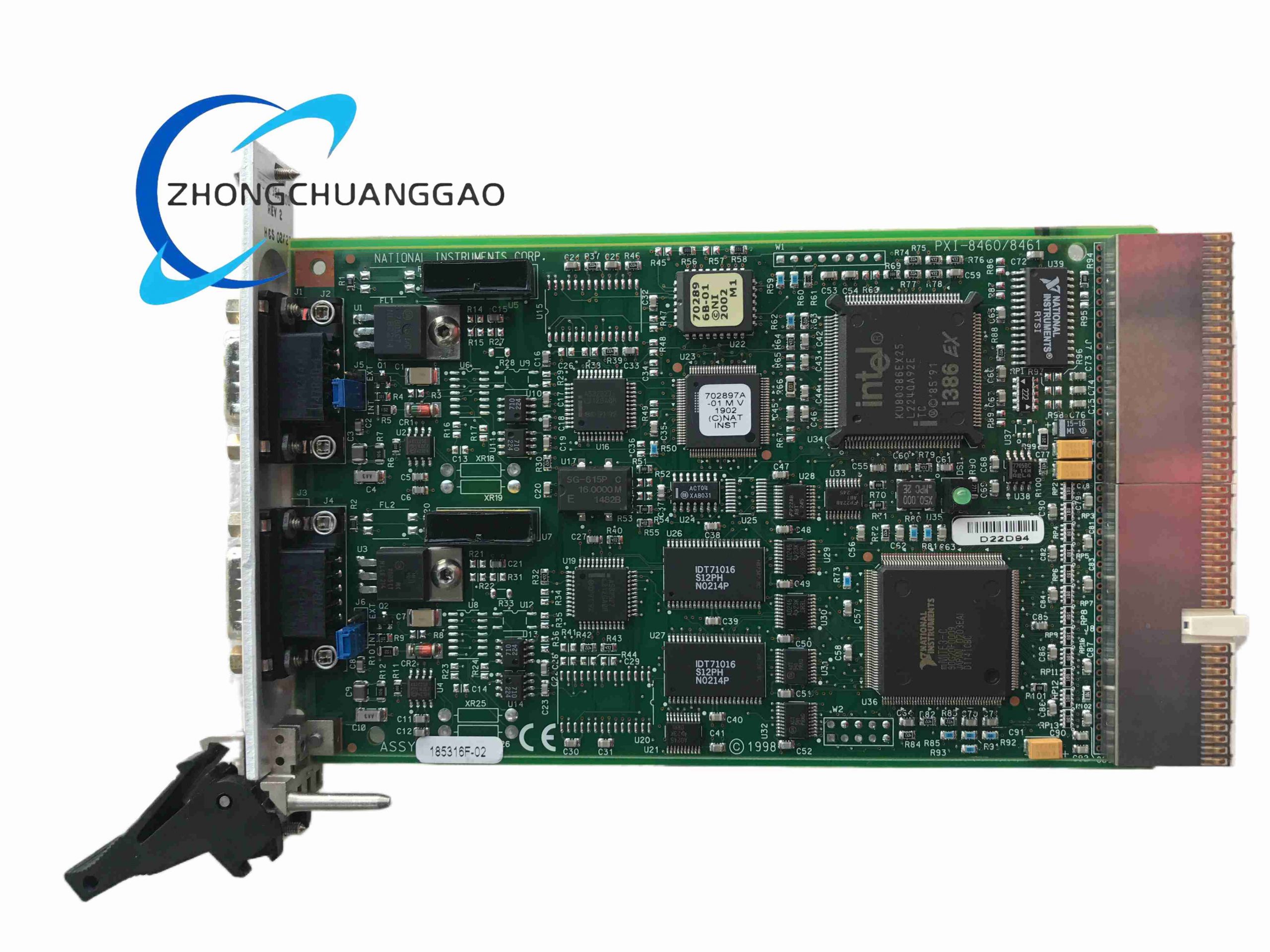
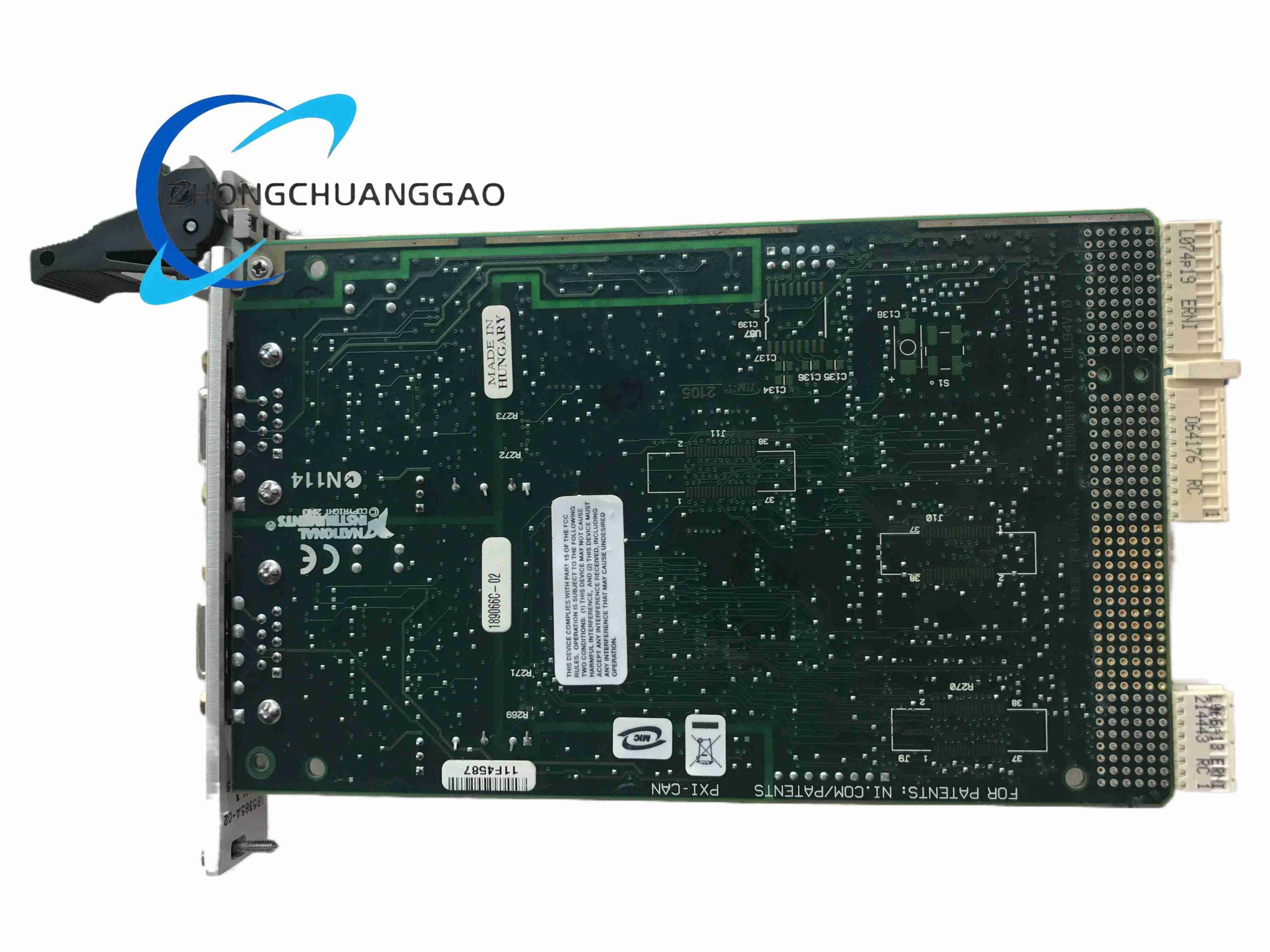
Description
Technical Specifications
- Protocol: CAN 2.0A and CAN 2.0B
- Physical Layer: ISO 11898-2 high-speed CAN
- Maximum Data Rate: 1 Mbit/s
- Port Variants: Single-port or dual-port
- Isolation: 500 V optical isolation typical
- Synchronization: RTSI and PXI trigger bus
- Driver: NI-CAN
- Operating Temperature: 0 °C to 55 °C
Functional Features
- Timestamped CAN frame capture
- Single- or dual-channel configurations
- RTSI synchronization with DAQ and timing modules
- NI-CAN API support
- LabVIEW and LabWindows/CVI integration
Working Principle
The module uses a CAN controller and physical transceiver to encode and decode CAN frames. Frames are moved through shared memory and interrupts to the host, while timestamp and trigger logic align CAN traffic with other PXI measurements.
Application Scenarios
- Automotive ECU testing
- Hardware-in-the-loop bench
- End-of-line vehicle test
- Battery management system test
- Body electronics validation
- Industrial CAN diagnostics
Installation Requirements
- Install in standard PXI chassis slot
- Use CAN twisted-pair cable
- Install NI-CAN driver
- Terminate CAN bus with 120 Ω resistors at both ends
- Verify node baud rate and identifiers
Usage Notes
- Do not operate without proper CAN termination at high speed
- Avoid connecting incompatible CAN voltage nodes
- Keep stub lengths short
- Use shielding with correct drain-wire grounding
- Confirm single-port or dual-port hardware variant before configuration
Reviews
There are no reviews yet.