
Product Short Description
Product Name:
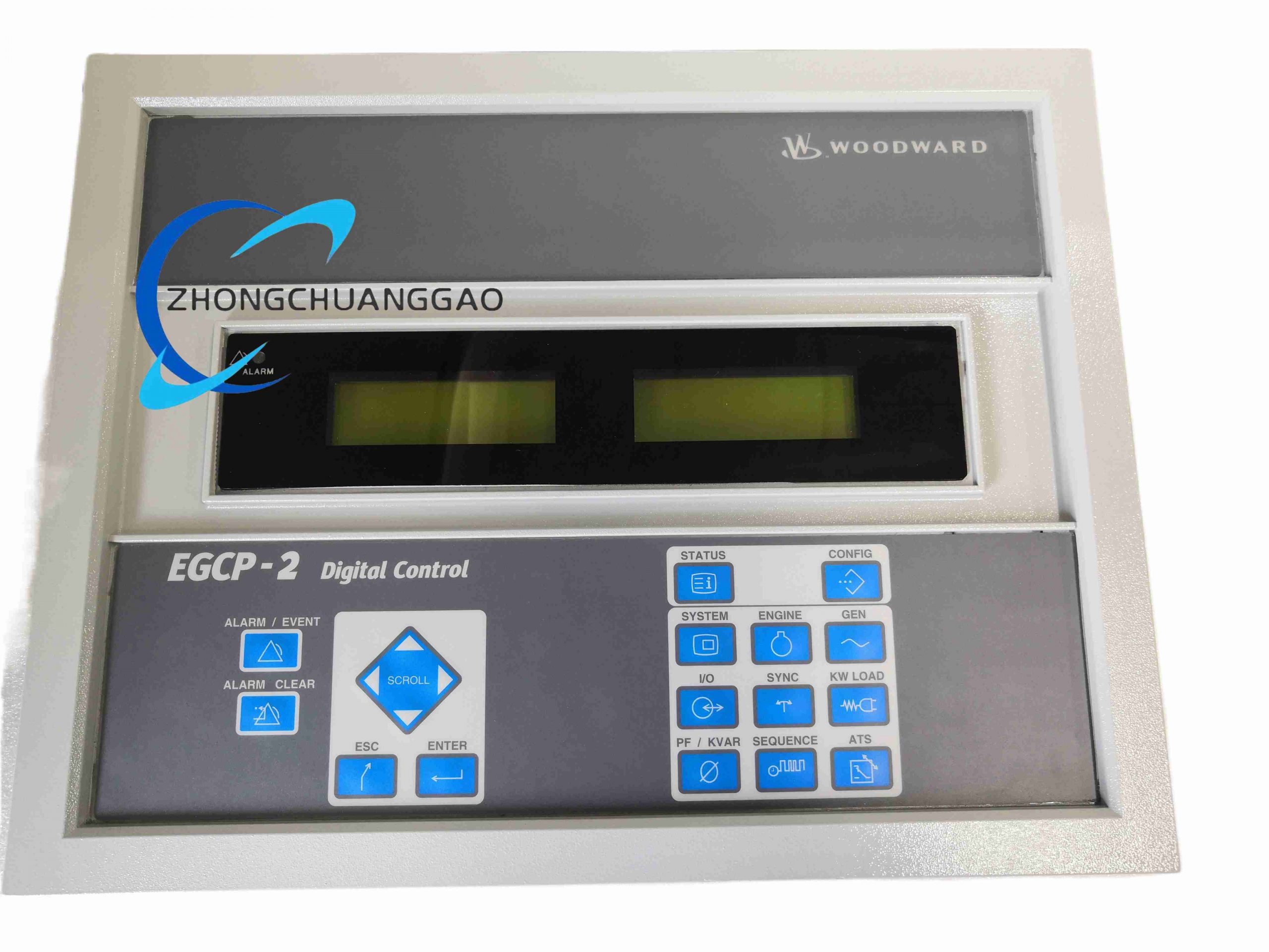
EGCP-2 8406-121 Microprocessor Engine Generator Control Package
Product Overview:
The package integrates engine governing, generator voltage control, synchronization, active and reactive load sharing, sequencing and protection in one microprocessor controller for diesel or gas generator sets.
Description
Technical Specifications:
Supply voltage 9 to 32 V DC, suitable for 12 V or 24 V systems. Power consumption 13 W nominal, 20 W maximum. Potential transformer input 50 to 150 V AC. Current transformer input 0 to 5 A RMS. Generator frequency range 40 to 70 Hz. Magnetic pickup input 100 to 1000 Hz. Discrete inputs 16 channels. Relay outputs 10 A at 250 V AC resistive and 10 A at 30 V DC resistive. Analog outputs include 4 to 20 mA, 0 to 10 V DC, plus or minus 3 V DC and plus or minus 9 V DC. Process inputs 4 to 20 mA and 1 to 5 V DC. Temperature and pressure inputs 0 to 200 ohm, 4 to 20 mA or 0 to 5 V. Communication Modbus RTU or ASCII over RS-422 or RS-485, EGCP-to-EGCP load-share network over RS-485. Display two backlit LCD units, 8 lines by 20 characters each, with membrane keypad. Enclosure performance IP56 when mounted in suitable vented enclosure, Type 4. Dimensions 282 mm height, 358 mm width, 69 mm depth. Operating temperature -20 to 70 C. Storage temperature -40 to 105 C. Relative humidity 95 percent non-condensing.
Functional Features:
Speed governing, voltage regulation, automatic start and stop, synchronizing, kW and kVAR load sharing, base-load and peak-shaving control, alarm and shutdown protection, data monitoring, network operation for up to 8 units.
Structure And Materials:
Panel-mounted coated enclosure, LCD screens, keypad membrane, terminal block for PT and CT inputs, relay board, microprocessor mainboard, communication transceivers, power supply section.
Working Principle:
The controller measures generator voltage through PT input and current through CT input. Engine speed is measured from magnetic pickup or AC frequency. The microprocessor adjusts governor and AVR commands, closes breakers after sync criteria are met, and shares active and reactive load with other EGCP units through the communication network.
Installation Requirements:
Mount on a generator control panel with the specified cutout and sealing gasket. Connect PT to generator voltage taps within 50 to 150 V AC. Connect CT secondaries rated 0 to 5 A. Provide 12 V or 24 V DC control power with proper fusing. Wire relay outputs to fuel solenoid, starter, breaker and alarm devices. Ground the enclosure.
Application Scenarios:
Standby power for hospitals and data centers, prime power for remote sites and mines, diesel or gas genset paralleling, peak-shaving systems and marine power plants.
Usage Precautions:
Verify PT ratio before connection because this model is configured for 50 to 150 V AC PT input. Do not open CT secondary circuits under load. Keep humidity below 95 percent and avoid condensation. Use Woodward configuration software and approved communication cables. Inspect relays and wiring regularly.
-500x500.jpg)
Reviews
There are no reviews yet.