
Product Short Description
Product Overview
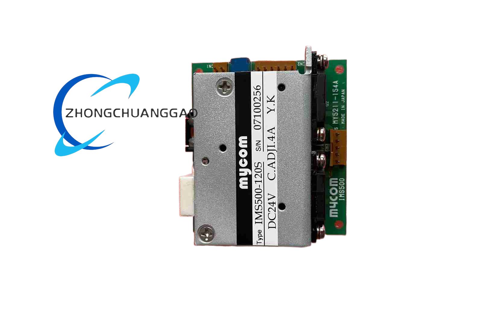
The IMS500-120 series is a super-compact five-phase stepping system intended for precise pulse-controlled positioning. The 120-class driver supplies up to 1.4 A per phase from a 24 V DC supply and operates with MYCOM five-phase stepping motors in factory automation, instrument positioning and motion-control applications.
Description
Technical Specifications
Power supply is DC 24 V ±10 percent. Drive method is star-bipolar five-phase output. Maximum output current is 1.4 A per phase. Resolution supports full and half step; basic step angle depends on the connected five-phase motor and is 0.72 degree or 0.36 degree. Control inputs are photoelectric coupler inputs with 220 ohm input resistance. Input signal levels are L 0 to 0.5 V and H 4 to 5 V. CW terminal accepts pulse commands; CCW terminal accepts direction commands in single-pulse mode or reverse/forward pulses in double-pulse mode; CO terminal controls excitation on/off with H level excitation-off and L level excitation-on. Auto current-down and output-current-off functions are provided.
Functional Features
Ultra-compact body, selectable excitation mode, selectable pulse input mode, automatic current reduction at standstill or no-pulse conditions, and photoelectric isolation between control signals and power stage.
Applications
Small CNC stages, semiconductor handling equipment, laboratory instrumentation, valve and damper positioning, packaging machines, and industrial fixtures requiring low-vibration five-phase motion.
Construction And Materials
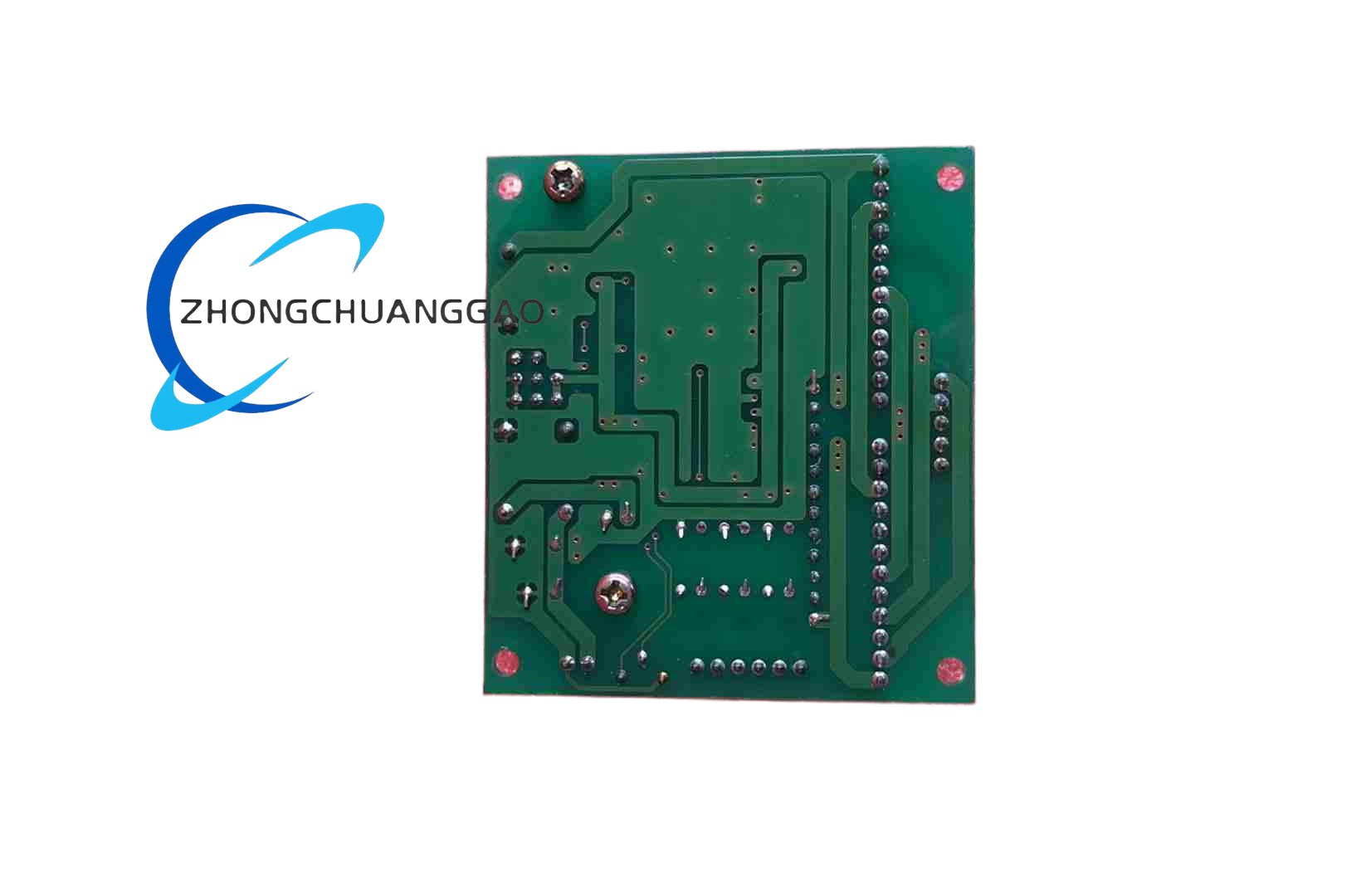
Driver body dimensions are 67.0 mm × 60.0 mm × 24.6 mm. Driver mass is approximately 75 g. The unit uses a printed circuit board, power semiconductor stage, heat-conductive baseplate/heatsink area, photoelectric input circuit and screw or plug terminals according to the ordered set.
Working Principle
The controller sends CW/CCW pulses and CO enable signals. The driver converts these into sequenced five-phase stator currents through the star-bipolar bridge, produces microstepping or full/half steps according to the resolution setting, and automatically lowers current when the motor is static to reduce heat.
Installation Requirements
Mount the driver in a clean, ventilated control panel with clearance for heat dissipation. Use stabilized DC 24 V ±10 percent with adequate current margin for all phases. Separate motor cables from signal cables. Connect motor phase windings only to MYCOM-compatible five-phase motors rated for the 120-class current. Set excitation and pulse mode before energizing.
Precautions
Do not exceed 1.4 A per phase. Verify motor step angle and winding type before configuration. Maintain ambient temperature 0 to 40 °C and humidity below 80 percent without condensation or freezing. Keep storage temperature -10 to 60 °C. Confirm insulation resistance above 100 MΩ at DC 500 V between power/motor terminals and heatsink/signal terminals before return-to-service. Avoid cable routing that exposes low-voltage signal inputs to noise or high-voltage transient.
Reviews
There are no reviews yet.