
Product Short Description
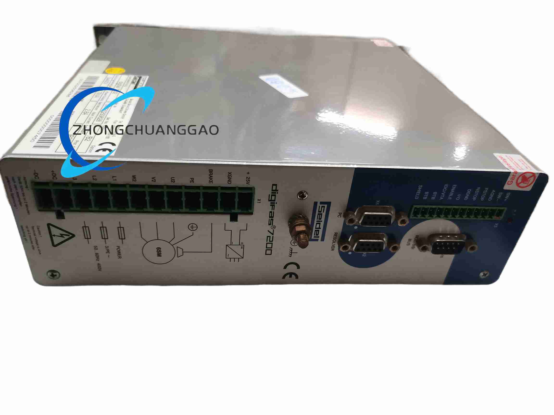
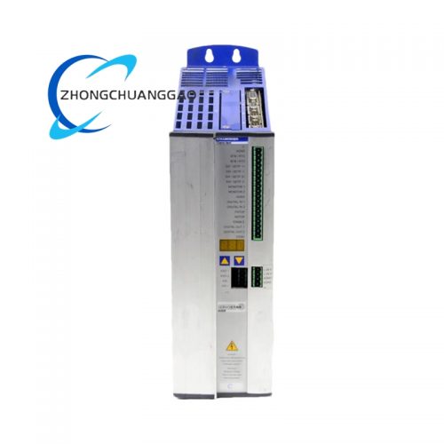
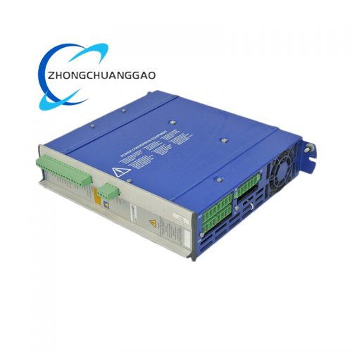
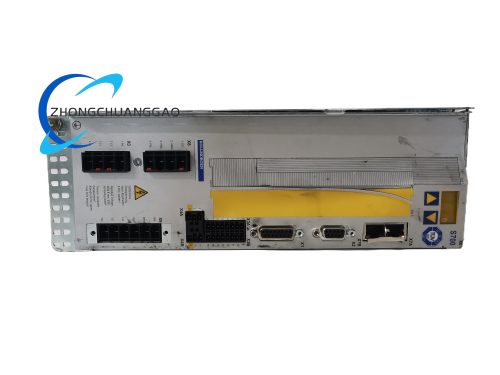
Product Name: Kollmorgen (Berger Lahr) DIGIFAS-7202 — Digital Servo Drive / Servo Amplifier (DIGIFAS 7200 family)
Product Overview: The DIGIFAS-7202 is a compact single-axis digital servo amplifier from the DIGIFAS 7200 family (originally Berger Lahr, later aligned under Schneider Electric/Kollmorgen). It is designed to drive AC synchronous / BLDC servo motors with precise positioning and speed control. It is commonly used with Berger Lahr servo motors and is well-suited for retrofit projects thanks to its compatibility with ±10 V analog and step/direction control signals.
Description
Technical Specifications (typical for the 7200 family / DIGIFAS-7202):
- Product Type: Digital servo amplifier for AC synchronous / BLDC motors
- Main Supply: 230 VAC class, 50/60 Hz (variant-dependent; some versions support 3 × 80–400 VAC)
- DC Bus Voltage: 560 VDC nominal (for 400 VAC versions)
- Control Supply: 24 VDC (typical)
- Rated Output Current: 2.8 A RMS (varies by version)
- Peak Output Current: 5.6 A RMS (max 5 s)
- Current Controller Bandwidth: 1 kHz
- Output Stage Switching Frequency: 8.33 kHz
- Minimum Motor Inductance: 5 mH
- Quiescent Loss: 15 W; Loss at Rated Current: 45 W
- Communication: RS-232 service/parameter port; optional fieldbus variants (CANopen, Profibus, SERCOS) depending on model
- Feedback Support: Incremental encoder or resolver (version-dependent)
- Signal I/O: ±10 V analog, step/direction; digital enable/inhibit, home/limit inputs
- Operating Temperature: 0 … 40 °C in ventilated control cabinet
- Weight: ~0.26 kg
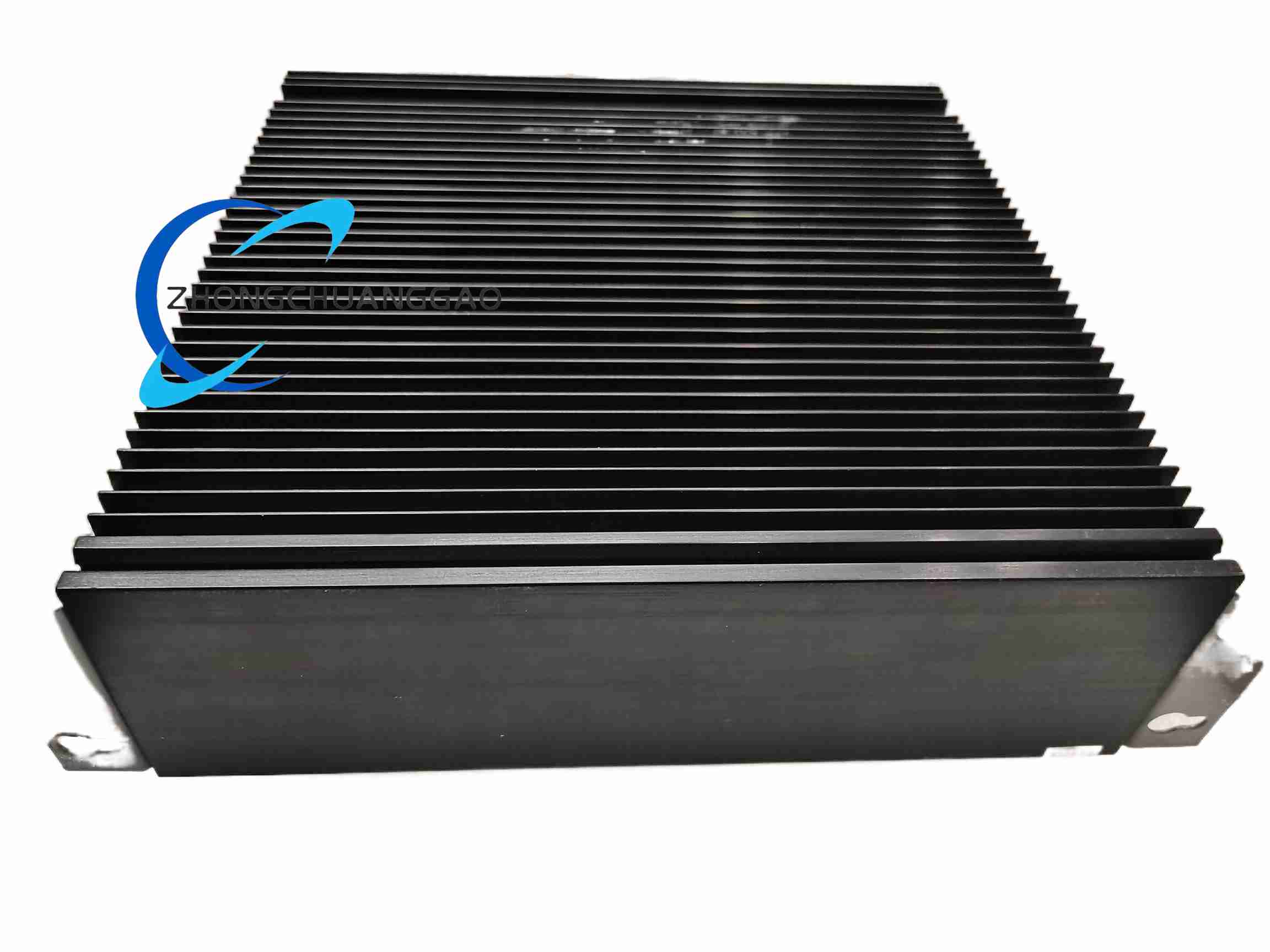
- Mounting: Panel/cabinet mounting
Key Features: Multiple command modes (torque, velocity, position); drop-in compatibility with legacy Berger Lahr motor/feedback sets; friendly with ±10 V analog and step/direction signals for easy retrofits; integrated brake control for vertical axes; RS-232 for parameter backup and commissioning.
Application Scenarios: Packaging lines, labeling stations, light-duty robotics, electronics assembly, printing/marking, conveyor indexing, pick-and-place axes, web tension control, and retrofit projects where PLC sends ±10 V or step/direction signals.
Installation & Usage Notes: Mount in a ventilated, clean control cabinet with proper grounding and EMC practices. Shield motor and signal cables. Connect to appropriate mains supply per variant. Parameter backup via RS-232. Ensure adequate cooling clearance; observe operating temperature limits.
Reviews
There are no reviews yet.