
Product Short Description
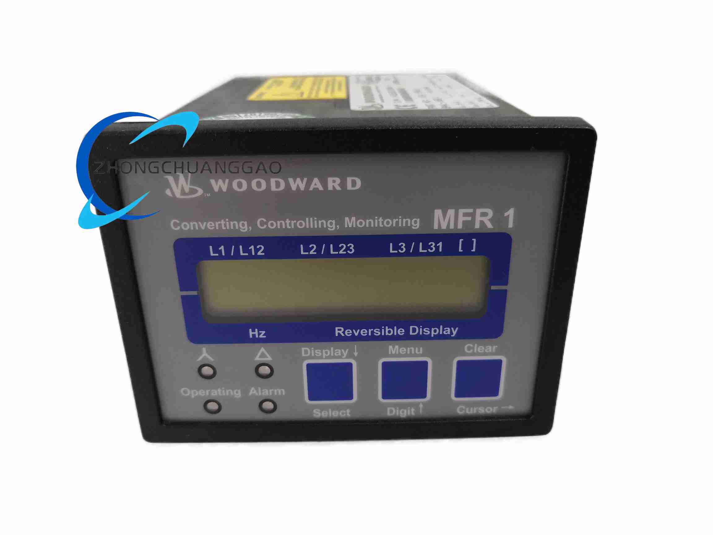
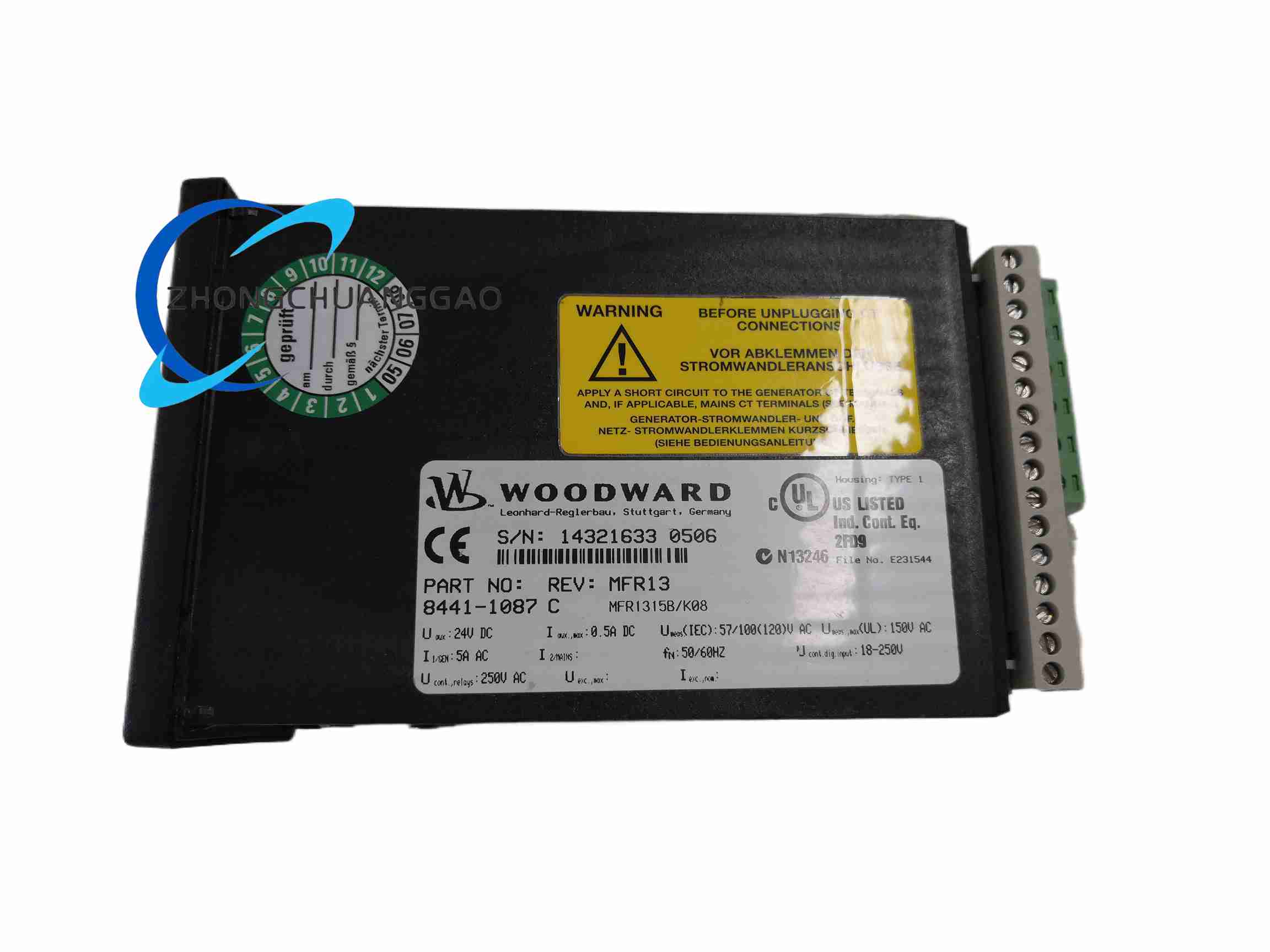
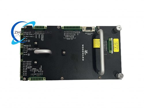
Product Name: Digital Governor / Turbine Protection Controller (ProTech™ GII family)
Product Overview:
A microprocessor‑based control and protection device intended for steam turbines, gas turbines, compressor drives, and generator set management. It executes speed/load control while simultaneously performing overspeed, vibration, axial‑shift, and temperature protection with trip relay output.
Description
Technical Specifications:
|
Parameter
|
Specification
|
|---|---|
|
Power Supply
|
24 V DC
|
|
Input Signals
|
Magnetic pickup (speed), 4‑20 mA (vibration/displacement), RTD (temperature)
|
|
Voting Logic
|
2oo3 / 2oo4 redundant voting
|
|
Outputs
|
Solid‑state trip relays, 4‑20 mA analog monitoring
|
|
Communication
|
Modbus RTU (RS‑485) / Modbus TCP (optional), independent RS‑232 & RS‑422
|
|
Safety Level
|
IEC 61508 SIL 2
|
|
Display
|
Integrated LCD showing measurements, alarms, event history
|
|
Operating Temp.
|
‑20 °C to +60 °C
|
|
Protection
|
Front IP65 / Body IP20
|
|
Mounting
|
Panel mount (¼ DIN) or DIN rail
|
Functional Features:
-
Speed & Load Control – Configures diesel/gas engine speed or load; supports soft load transfer, torque limiting, MAP limiting, low‑speed sensing, and adaptive speed sensing algorithms.
-
Multi‑Engine Governing – Suitable for industrial engines, steam turbines, gas turbines, dual‑fuel turbines, compressors, and turbo‑expanders.
-
Protection Functions – Overspeed, vibration, axial displacement, temperature; triggers shutdown (trip) upon dangerous condition.
-
Diagnostics – Local LCD display, data logging capability, Modbus reporting.
-
Redundant Communication – Built‑in redundant Ethernet ports plus two serial ports.
Application Scenarios: Oil & gas production, power generation, industrial turbomachinery, marine propulsion auxiliaries, and process plants requiring SIL‑rated trip protection.
Working Principle: Continuously samples magnetic‑pickup speed pulses and analog transducer inputs, evaluates them against configurable setpoints, and drives a solid‑state trip relay when a voted dangerous condition is detected; speed control is closed‑loop via PWM or analog governor bias.
Installation Requirements: Mount in a control cabinet with clean, dry air; ensure 24 V DC supply is isolated and noise‑filtered; route field wiring away from high‑voltage conductors; ground the enclosure to plant earth.
Usage Notes: Do not bypass the trip relay in running condition; verify voting configuration before energizing; periodic functional test of the trip path is mandatory; firmware changes require engineering approval.
Reviews
There are no reviews yet.