
Product Short Description
Product Name
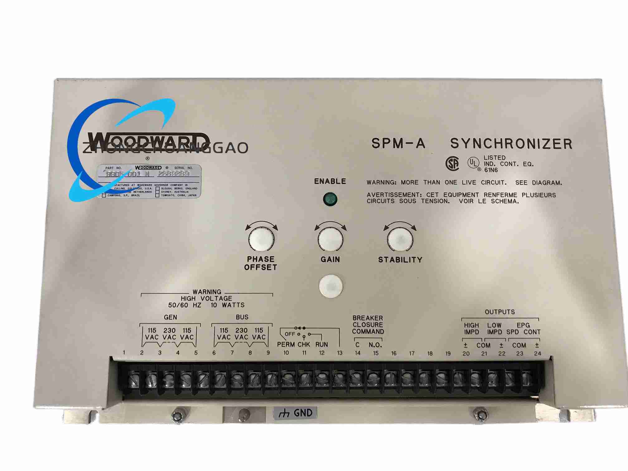
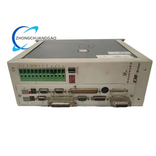
SPM-A Automatic Synchronizer
Product Introduction
The Woodward 9905-001 SPM-A is an automatic synchronizer module designed to match the phase, frequency, and voltage of a generator to the bus before closing the breaker. It compares generator and bus signals in real time, then issues raise/lower commands to the speed governor and voltage regulator to bring the two systems into alignment. When sync conditions are satisfied, the module closes a “sync check” relay to permit breaker closure.
Description
Technical Specifications
-
Supply Voltage: 24 V DC (typical)
-
Frequency Range: 45–65 Hz
-
Voltage Input: 90–150 V AC (PT-derived)
-
Phase Sync Range: ±40° auto-correction
-
Speed Control Output: ±3 V DC (to governor)
-
Voltage Control Output: ±5 V DC (to AVR)
-
Response Time: <50 ms
-
Operating Temperature: −20 °C to +70 °C
-
Protection: IP54 (when installed inside control cabinet)
-
Weight: 1.8 kg
-
Mounting: Panel or control cabinet backplate
Functional Features
-
Automatic phase, frequency, and voltage matching.
-
High-precision comparison circuitry minimizes paralleling error.
-
Compatible with most Woodward or third-party governors and AVRs.
-
Built-in protection: blocks synchronization on over-voltage, under-frequency, or phase-angle out-of-limit.
-
Analog and relay outputs for easy integration into PLC/DCS.
-
Manual/automatic mode switch for commissioning or special conditions.
-
Industrial-grade PCB with enhanced anti-vibration, EMI resistance, and salt-spray tolerance.
Application Scenarios
-
Marine Power: Multi-generator paralleling for shipboard stability.
-
Industrial Power Plants: Generator-to-grid synchronization.
-
Backup Power Systems: Automatic paralleling of standby generators.
Working Principle
The synchronizer continuously samples generator and bus voltage via PT inputs. It measures frequency difference, phase-angle difference, and voltage magnitude difference. Based on these errors, it outputs a ±3 V DC signal to the governor to adjust speed, and a ±5 V DC signal to the AVR to adjust excitation. When all three parameters fall within the preset windows, the sync-check relay energizes to allow breaker closure.
Installation Requirements
-
Mount on panel or cabinet backplate; ensure IP54 environment.
-
Connect PT input from generator and system bus.
-
Wire “Frequency Adjust” (Raise/Lower) to governor input.
-
Wire “Voltage Adjust” to AVR input.
-
Wire “Sync Check Relay” contact to breaker close coil.
-
Confirm control cabinet grounding to avoid noise interference.
Usage Precautions
-
Verify PT polarity and ratio before energizing.
-
Check that supply voltage matches 24 V DC nominal.
-
Do not operate outside −20 °C to +70 °C.
-
Inspect terminal tightness every 3–6 months.
-
Keep surface dust-free and ventilation unobstructed.
-
Monitor sync time history; abnormal increase indicates potential fault.
Reviews
There are no reviews yet.