
Product Short Description
Product Introduction:
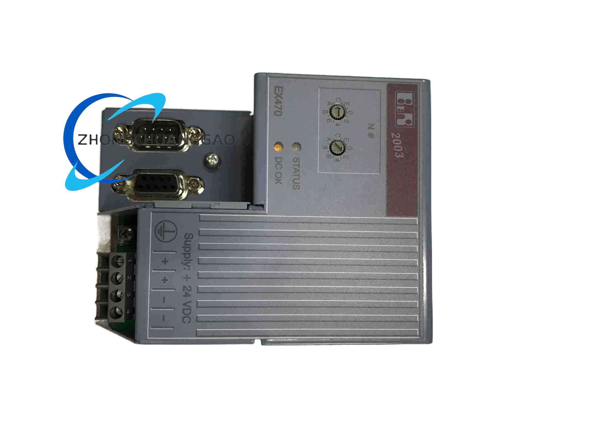
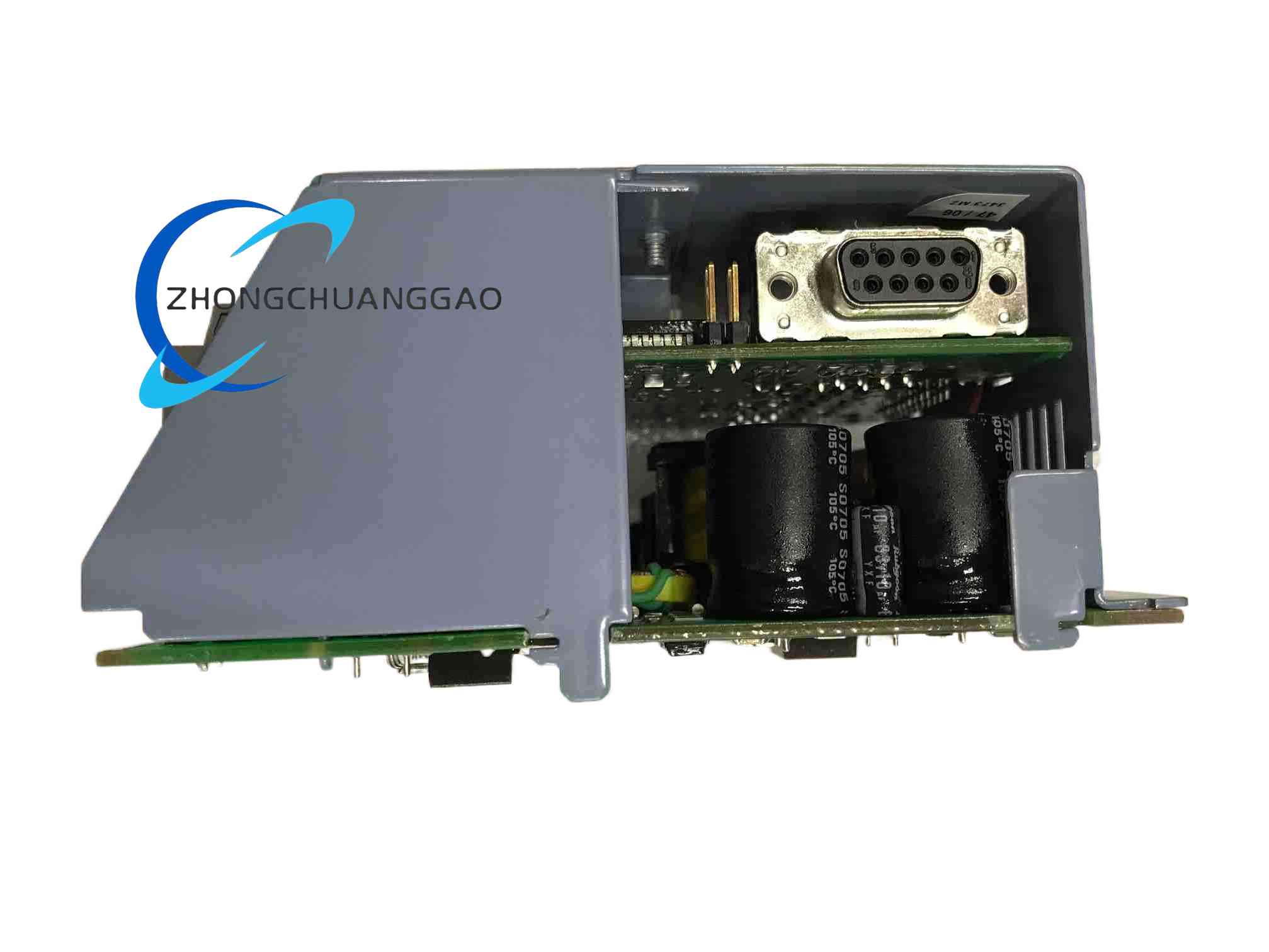
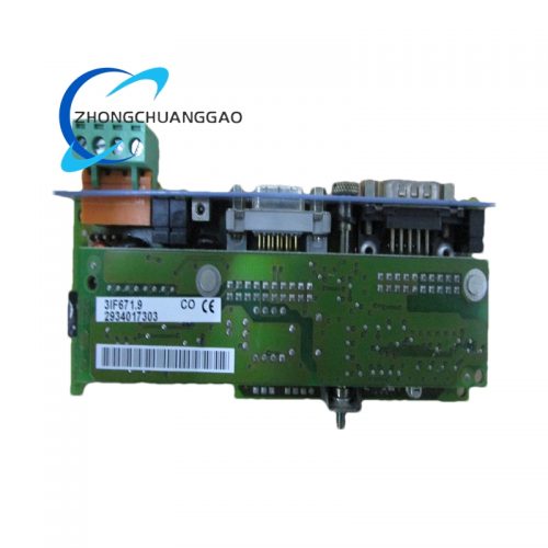
The 7EX470.50‑1 is a CAN bus controller and power supply module for the B&R SYSTEM 2003. It acts as a remote CAN slave, converting cyclic CAN packets into local backplane communication for adjacent digital and analog I/O modules, while providing up to 14.5 W of regulated 24 VDC power to the expansion rack.
Description
Technical Specifications:
|
Parameter
|
Value
|
|---|---|
|
Input voltage
|
18 VDC (min) / 24 VDC (nom) / 30 VDC (max)
|
|
Power consumption
|
Max. 20 W
|
|
Output power for I/O modules
|
14.5 W (max)
|
|
CAN interface IF1
|
9‑pin D‑sub plug, electrically isolated, 1000 m max. distance, 500 kBaud max.
|
|
CAN interface IF2
|
9‑pin D‑sub socket, electrically isolated, 1000 m max. distance, 500 kBaud max.
|
|
Node addressing
|
Rotary number switch on module front
|
|
Diagnosis LEDs
|
Yes (STATUS two‑colour LED + voltage alarm)
|
|
Module width
|
B&R 2003 single width
|
|
Slot requirement
|
1
|
|
Operating temperature
|
0 °C to +60 °C
|
|
Certification
|
C‑UL‑US listed
|
|
Network capability
|
Yes
|
Functional Features:
-
Dual isolated CAN interfaces for daisy‑chain networking
-
Integrated 24 VDC power stage eliminates need for separate power supply at remote rack
-
STATUS LED indicates boot phase, normal operation, output faults, and voltage alarms via blink codes
-
When a CAN object fails to arrive within the watchdog time (default 640 ms), affected outputs are reset and the green LED blinks with double pulse
Working Principle:
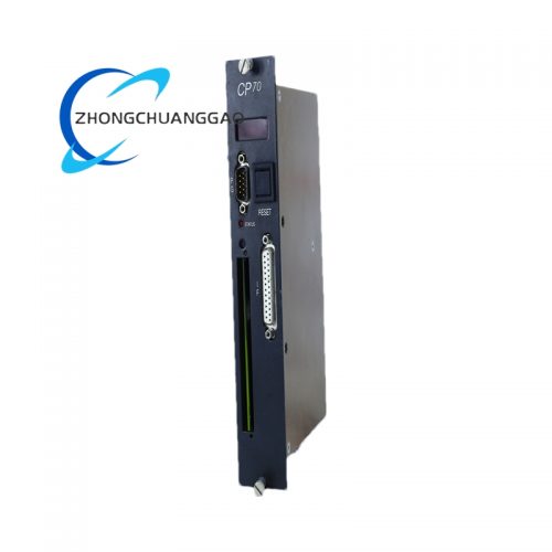
The module operates strictly as a fieldbus gateway. The primary SYSTEM 2003 CPU (e.g., 7CP476) scans the CAN topology, identifies the 7EX470 by its rotary switch address, and maps its attached I/O cards directly into the central PLC image table. No local ladder logic is stored on the EX470 itself.
Application Scenarios:
-
Decentralized I/O for long linear machines (printing presses, bottling lines, modular packaging systems)
-
Remote I/O sub‑racks located at actuator level to avoid long parallel wiring
-
Bridge between central CPU and distributed 2003 expansion racks
Installation Requirements:
-
Insert in the leftmost slot of a SYSTEM 2003 expansion rack
-
Set node address via front rotary switches (00–FF hex)
-
24 VDC supply within 18–30 VDC
-
DIN‑rail or panel mount within a control cabinet
Usage Precautions:
-
The last 7EX470 slave node on the CAN trunk MUST have a 120 Ω termination resistor at the open CAN OUT port, otherwise communication errors will occur
-
Total I/O module load must not exceed 14.5 W supplied by the controller
-
Do not exceed 0–60 °C operating envelope; derating applies at altitude > 500 m
Reviews
There are no reviews yet.