-
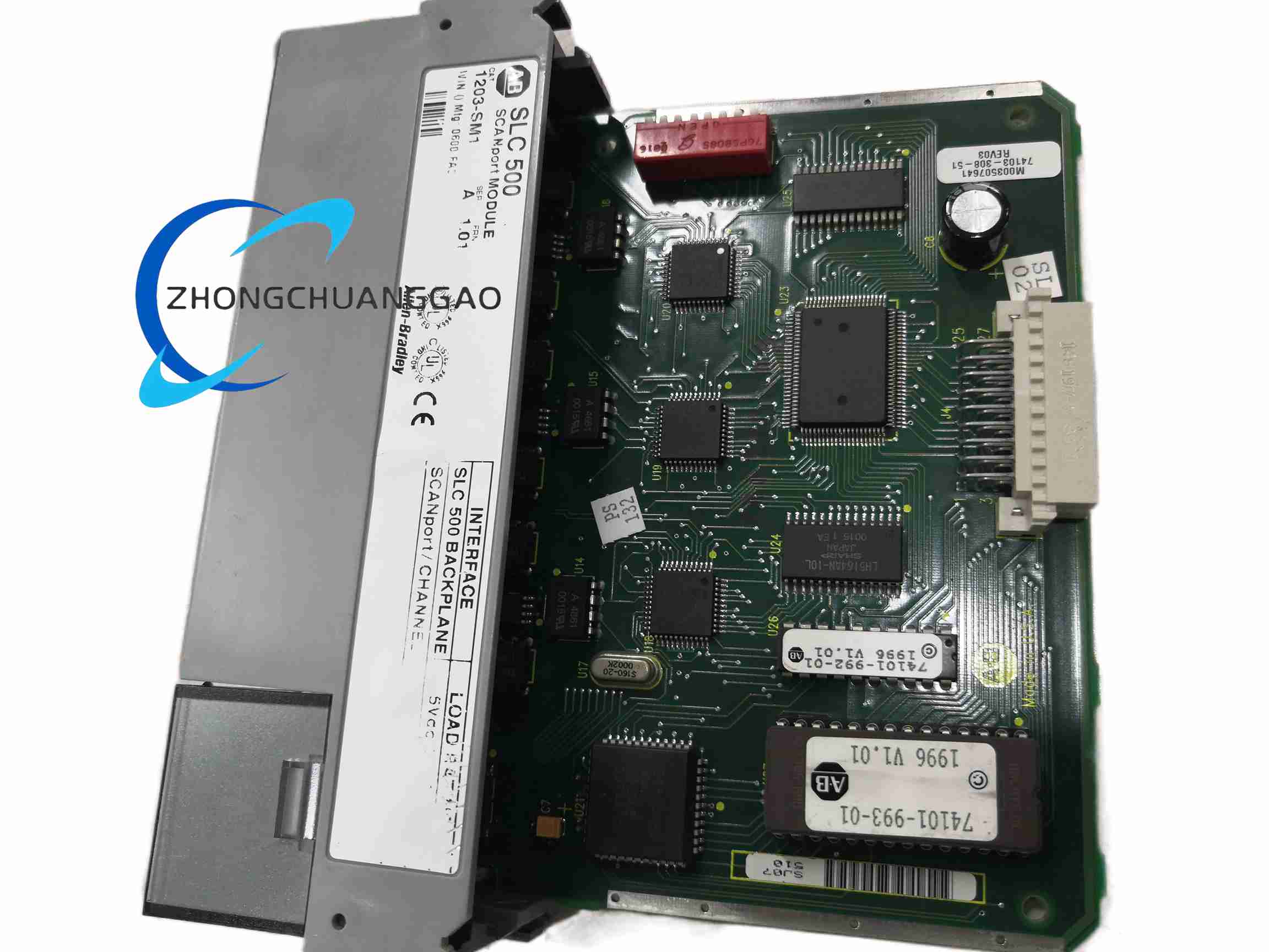
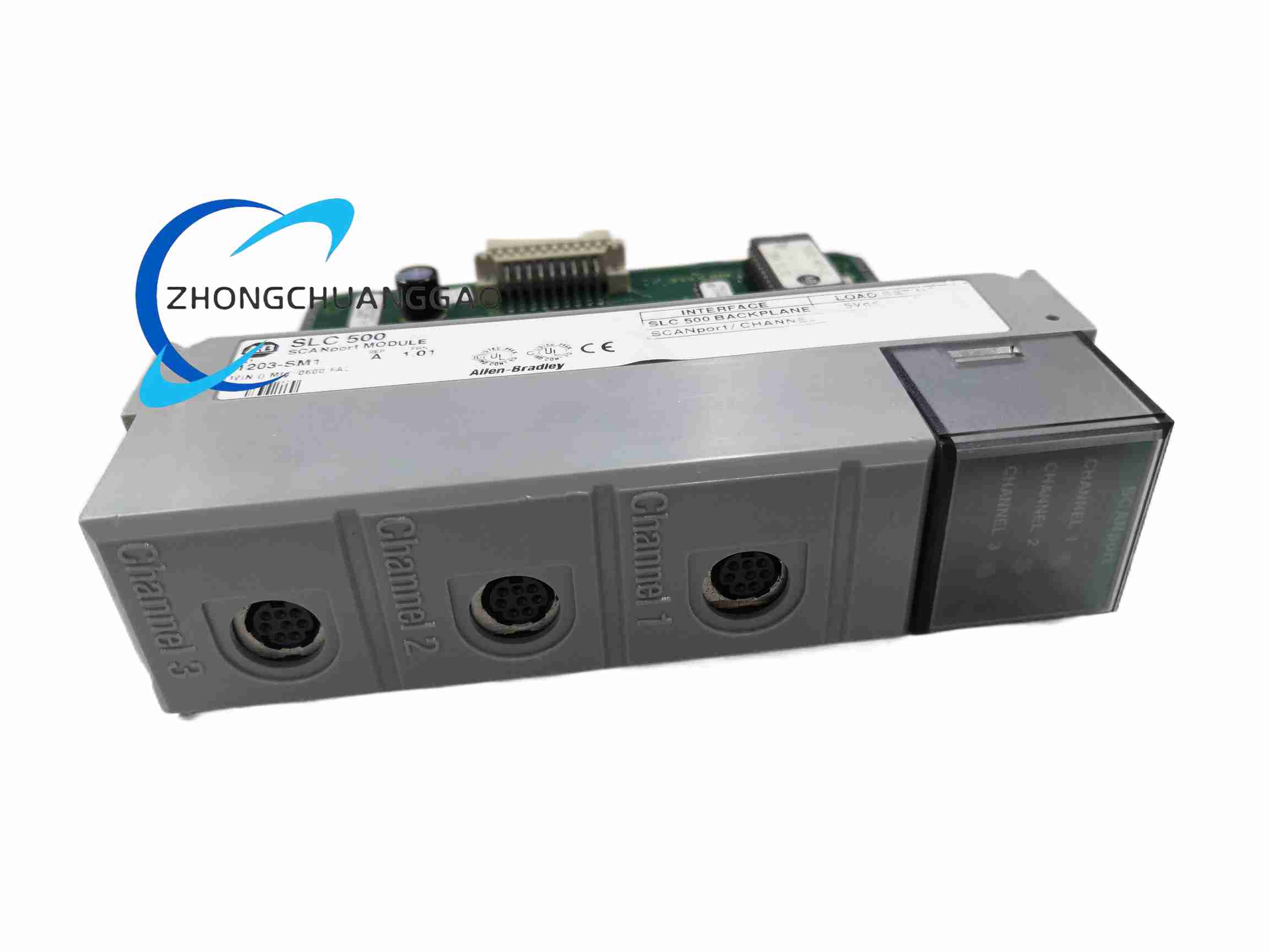
Channel Ports: 3 round SCANport connectors (for daisy-chaining multiple drives)
-
Compatible Drives: Allen-Bradley 1305 Series A & B AC drives (Series B requires firmware v3.001+ for full SCANport support)
-
Mounting: Chassis-mounted inside the 1305 drive (NOT DIN-rail)
-
Status Indication: 3 channel LED indicators (Green = active communication; Amber = no link; Off = no power)
-
Data Transfer Modes:
-
Basic Mode: Simple peer-to-peer data transfer via integer file I/O image
-
Enhanced Mode: Datalinks, safe-state configuration, SCANport messaging via G-files & M-files
-
Supported Messaging: Read/write parameter values, restore/save to non-volatile storage, scaling formulas, read product info
-
Manual Reference: 1305-UM-001 (available on AB.com)
-
European Union Compliance: EMC Directive, Low Voltage Directive
-
⚠️ Lifecycle Notice: Officially obsolete per A-B publication PN405 (Jan 2012). Migration path: PowerFlex 525 with embedded comms, or 20-COMM-x modules for PowerFlex 4-class drives.
-
Installation Steps:
-
Determine SCANport cable length (use A-B 1202-C10 or 1202-C30 cables — generic RJ45 will NOT work due to proprietary pinout)
-
Plan cable placement to avoid EMI sources
-
Locate DIP switch for node addressing
-
Seat module into the 1305 drive chassis until locked
-
Configure Basic or Enhanced mode via Rockwell APS software
-
Troubleshooting:
-
Channel LEDs: Green = normal; Amber = no link; Off = no power
-
Verify cable integrity with A-B 1202-series SCANport cables only
-
Confirm 1305 Series B firmware ≥ v3.001 for full SCANport functionality
-
⚠️ Common Mistake: Field drawings sometimes reference “1746-SM1” — that catalog number does NOT exist in the A-B catalog; the correct part is 1203-SM1.

Reviews
There are no reviews yet.