
Product Short Description
Product Overview
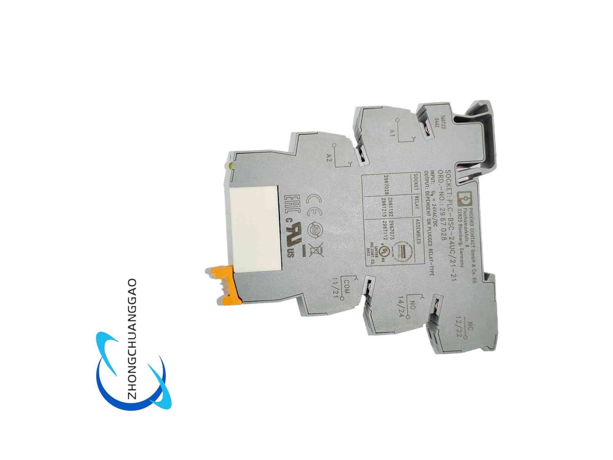
Description
Core Technical & Performance Specifications
- Control Coil Electrical Parameters
- Rated control coil operating voltage: 24V universal AC/DC (compatible with 24VDC PLC digital output and 24VAC auxiliary control circuit)
- Allowable coil voltage fluctuation range: 80% ~ 110% of rated 24V voltage
- Rated coil power consumption: 0.7W DC / 0.9VA AC
- Coil surge suppression configuration: Built-in bidirectional TVS transient voltage suppression diode integrated inside the base socket, automatically absorb the reverse electromotive force generated when the coil power supply is cut off to avoid surge voltage backflow damage to PLC output chips
- Coil status indication: Embedded red high-brightness LED indicator on the front of the module; LED lights up continuously when the coil is energized and the relay contact is closed, and turns off when the coil is de-energized and the contact resets
- Load Contact Electrical Performance Parameters
- Contact structure form: Single-pole normally open (1NO) single contact
- Rated contact switching load capacity:
Resistive load: 6A / 250VAC; 6A / 30VDC
Inductive load (electromagnetic valve, contactor coil): 3A / 250VAC
- Minimum reliable switching load: 1mA / 5VDC (suitable for low-current signal switching scenarios)
- Contact mechanical service life: 100,000,000 times no-load switching
- Contact electrical service life: 100,000 times switching under rated 6A resistive load
- Contact insulation withstand voltage: 5,000VAC between control coil circuit and load contact circuit for 1 minute without breakdown, realizing complete electrical isolation between control side and load side
- Mechanical & Physical Dimension Parameters
- Standard module width: 6.2mm narrow single module
- Overall external dimensions: 80mm height × 6.2mm width × 94mm depth
- Single module net weight: 32g
- Installation standard: Compatible with standard 35mm top-hat DIN mounting rails in accordance with EN 60715 international standard
- Wiring terminal type: M3 screw clamp wiring terminals for both control coil circuit and load contact circuit, wire clamping range 0.08mm² ~ 2.5mm² solid copper wire / stranded copper wire with wire end ferrules
- Environmental Working Parameters
- Continuous operating ambient temperature range: -40°C ~ +70°C
- Storage and transportation temperature range: -45°C ~ +85°C
- Allowable relative humidity range: 5% ~ 95% non-condensing
- Vibration resistance standard: IEC 60068-2-6, withstand 10Hz ~ 150Hz continuous vibration, 5g vibration acceleration
- Shock resistance standard: IEC 60068-2-27, withstand 30g peak instantaneous mechanical shock, 6ms pulse width
- Flame retardant grade of plastic housing: UL94-V0 highest flame retardant standard
- Electromagnetic compatibility certification: Comply with EN 61000-6-2 industrial equipment anti-interference standard, CE safety certification, UL industrial control component safety certification
- Insulation & Safety Performance Parameters
- Creepage distance between control coil and load contact: ≥8mm
- Clearance distance between control coil and load contact: ≥6mm
- Dielectric strength between adjacent wiring terminals: 2,000VAC withstand voltage without breakdown
- Protection grade of module housing: IP20, suitable for installation inside closed dustproof industrial control cabinets (direct exposure to splashing liquid and conductive metal dust is prohibited)
Material Composition
-
Integrated Base Socket Outer Housing
Adopt high-strength glass fiber reinforced PA66 nylon engineering plastic with UL94-V0 flame retardant grade, injection molded integrated one-piece shell structure. The material has excellent high-temperature resistance, impact resistance and aging resistance, will not deform or melt under long-term cabinet high-temperature operating environment, and will not produce open flame combustion when exposed to transient high-temperature electric arc generated by contact switching. The surface of the plastic shell adopts matte anti-slip texture treatment, and the inner wall of the shell is equipped with integrated positioning reinforcing ribs to fix the internal relay core and wiring terminal metal components tightly to avoid loose internal parts caused by equipment vibration.
-
Electromagnetic Relay Core Internal Components
- Relay coil skeleton: High-temperature resistant thermosetting bakelite plastic, with tightly wound enameled copper coil wires. The enameled wire surface is coated with high-temperature resistant insulating paint to prevent inter-turn short circuit faults of the coil under long-term energization heating.
- Electromagnetic iron core and armature: High-permeability soft silicon steel sheet stacked and riveted integrated magnetic circuit assembly, surface passivation anti-rust treatment. The silicon steel sheet material has low magnetic hysteresis loss, ensuring stable electromagnetic suction force of the coil under the full 24V AC/DC voltage fluctuation range, and rapid armature reset action after coil power failure.
- Contact spring reed assembly: High elastic beryllium copper alloy spring reeds with silver alloy contact points welded at the contact end. Silver alloy contact material has extremely low contact resistance, excellent arc ablation resistance and anti-sticking performance, effectively avoiding contact melting adhesion failure caused by electric arc generated during frequent inductive load switching. The beryllium copper spring reed maintains stable elastic contact pressure after millions of switching cycles to prevent poor contact and signal interruption faults.
-
Wiring Terminal Metal Components
All screw clamp wiring terminals are made of high-purity brass alloy base material with full nickel plating anti-oxidation and anti-corrosion surface treatment. The terminal internal clamping spring pieces are stainless steel elastic shrapnel, which provide constant clamping force on copper wires after screw tightening, preventing wire loosening caused by thermal expansion and cold contraction of wires under long-term current heating and cabinet mechanical vibration. The M3 terminal screw is made of carbon steel with black anti-rust surface coating, with cross and straight dual-purpose screwdriver slot design to adapt to different maintenance tool types.
-
Internal Surge Suppression & Indicator Electronic Components
- Bidirectional TVS surge suppression diode: SMD surface mount miniature semiconductor chip, welded on the base socket internal PCB circuit board, connected in parallel at both ends of the relay coil to absorb reverse electromotive force surge voltage.
- Red LED status indicator chip: High-brightness low-power gallium arsenide light-emitting diode, equipped with current-limiting series resistance to stabilize LED luminous brightness under 80% ~ 110% coil voltage fluctuation range, no LED burnout caused by excessive voltage.
- Internal miniature single-sided PCB substrate: FR-4 flame retardant thin printed circuit board, full immersion tin anti-oxidation treatment for welding pads, used to realize electrical connection between coil wiring terminals, LED indicator, TVS diode and relay coil core.
- Auxiliary Sealing & Shock Absorption Materials
- EPDM ethylene propylene rubber small sealing gaskets embedded between the relay core and the base plastic shell, absorbing tiny vibration generated during relay contact switching to reduce mechanical operation noise of the module.
- Anti-slip foam rubber cushion strips at the bottom of the DIN rail clamping buckle, increasing friction between the module base and the DIN rail surface to prevent the module from sliding and shifting on the mounting rail under long-term cabinet vibration.
Structural Feature
-
Ultra-Narrow 6.2mm Single-Module DIN Rail Integrated Plug-In Split Structure
The entire PLC-RSC-24UC module is composed of two detachable independent parts: replaceable electromagnetic relay plug-in core and fixed integrated wiring base socket. The relay core can be directly pulled out upward from the base socket without disassembling the wiring terminals or removing the module from the DIN rail during maintenance and replacement operations, which greatly shortens the on-site equipment fault maintenance downtime and avoids the need to rewire all control and load circuit cables after module replacement. The 6.2mm ultra-narrow single-module width enables dense multi-module side-by-side installation on standard 35mm DIN rails inside control cabinets, reducing the overall occupied cabinet space by more than 60% compared with traditional wide-width intermediate relays.
-
Front Panel Zoned Functional Layout with Visual Status Indication
The front vertical surface of the plastic base shell is divided into two independent upper and lower functional zones: the upper built-in red LED coil energization status indicator window, the lower engraved text marking area for circuit terminal definition and product model identification. The LED indicator window adopts transparent scratch-resistant PMMA acrylic lens integrated injection molded with the plastic shell, sealed with a tiny EPDM rubber gasket at the lens joint to prevent fine industrial dust from entering the internal LED chip position and blocking light transmission. The product model “PLC-RSC-24UC”, coil voltage parameter “24V UC” and terminal number identification texts are directly engraved on the matte plastic front panel surface, which will not wear off after long-term cabinet operation and frequent maintenance wiping, enabling maintenance personnel to quickly identify module specifications and circuit terminal definition without consulting product manuals.
-
Separate Isolated Dual-Circuit Wiring Terminal Partition Structure
The bottom part of the base plastic shell is divided into two completely isolated independent wiring terminal areas by an integrated plastic insulating partition plate: left side control coil circuit wiring terminal group (marked A1, A2), right side load contact circuit wiring terminal group (marked 13, 14). The thick solid plastic insulating partition plate between the two terminal areas forms a complete physical isolation barrier between the PLC low-voltage control coil circuit and the high-current field load contact circuit, greatly increasing the creepage distance and clearance distance between the two circuits to meet the 5000VAC high dielectric strength isolation safety standard. Each wiring terminal is equipped with an independent M3 screw clamp wire clamping structure, each terminal can independently clamp one single-strand or multi-strand copper wire, no shared wire clamping channels between adjacent terminals to avoid wire short-circuit faults caused by loose wire strands jumping between terminals.
-
Integrated Automatic Locking DIN Rail Mounting Buckle Structure
An integrated elastic plastic clamping buckle is injection molded at the bottom rear of the base plastic shell, specially matched with standard 35mm EN 60715 top-hat DIN mounting rails. The clamping buckle adopts one-way automatic locking spring structure: align the upper bayonet of the module base with the upper edge of the DIN rail, press the bottom of the module downward firmly, the elastic clamping buckle automatically retracts and rebounds to tightly clamp the lower edge of the DIN rail, completing rapid installation without additional fixing screws. When disassembly is required, use a flat-blade screwdriver to pry the small plastic pull tab at the bottom of the clamping buckle downward to release the locking spring force, then lift the bottom of the module upward to separate it from the DIN rail. The clamping buckle is integrated with the base plastic shell as a single piece without separate loose small parts, eliminating the risk of losing fixing buckles during maintenance disassembly operations.
-
Internal PCB Multi-Component Compact Integrated Circuit Layout
The thin FR-4 single-sided PCB circuit board is embedded in the middle interlayer of the base plastic shell, sandwiched between the relay plug-in core installation cavity and the bottom wiring terminal cavity. All internal electronic components including the TVS surge suppression diode, LED indicator chip and current-limiting resistance are directly surface-mounted on the front side of the PCB board. The PCB board reserves gold-plated spring contact shrapnel jacks at the top position corresponding to the relay plug-in core coil pins; when the relay core is inserted into the base cavity, the coil metal pins are tightly clamped by the gold-plated spring shrapnel to realize stable electrical connection between the relay coil and the base wiring terminal circuit. The back side of the PCB board is connected to each bottom wiring terminal metal component through short copper conductive jumpers, forming a complete independent electrical loop for the control coil circuit without cross-circuit signal crosstalk interference between the control circuit and the load circuit.
-
Relay Core Internal Magnetic Circuit Anti-Arc Isolation Structure
Inside the plug-in relay core, an integrated thin mica insulating arc partition plate is installed between the moving and static silver alloy contact points. The mica plate has excellent high-temperature arc ablation resistance; when the contact is switched on and off to break inductive load current, the electric arc generated between the contact points is blocked by the mica partition plate and cannot spread to the relay coil magnetic circuit assembly. This anti-arc isolation structure prevents the high-temperature electric arc from ablating the coil enameled wire insulating layer and causing coil inter-turn short circuit faults, greatly extending the overall electrical service life of the relay core under frequent inductive load switching working conditions. The top of the relay core plastic shell is reserved with a tiny pressure relief exhaust hole to discharge high-temperature gas generated by instantaneous electric arc inside the core, avoiding internal air pressure expansion damage to the relay plastic shell during long-term operation.
-
Multi-Layer Internal Vibration Damping Noise Reduction Structure
Multiple vibration damping auxiliary structures are designed inside the module to eliminate mechanical vibration and operation noise generated during relay contact switching. EPDM rubber elastic damping gaskets are laid at the contact surface between the relay plug-in core outer plastic shell and the base plastic shell inner wall, absorbing high-frequency vibration transmitted from the relay core to the base shell during contact switching. The armature moving part of the internal electromagnetic magnetic circuit assembly is equipped with a tiny silicone rubber buffer limit block at the reset stop position, which cushions the impact force generated when the armature rebounds and resets after coil power failure, reducing metal collision noise and slowing down the fatigue aging speed of the beryllium copper contact spring reed assembly. The bottom DIN rail clamping buckle is pasted with anti-slip foam rubber strips to isolate the vibration transmitted from the DIN rail to the module base shell, preventing vibration resonance amplification of mechanical noise between multiple adjacent relay modules installed side by side on the same DIN rail.
Reviews
There are no reviews yet.